
Operating Instructions

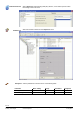
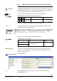
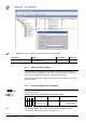
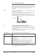
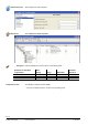
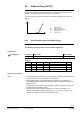
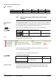
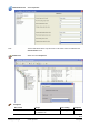
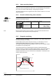
Table Of Contents
- RXB (KNX) applications library
- CLC and RAD description of functions for CC-02
- Table of contents
- 1 Introduction
- 2 Definitions / Tools
- 3 Select communications mode
- 4 Applications / Parameters
- 5 Room operating modes
- 5.1 Description
- 5.2 Overview
- 5.3 Determine the room operating mode with DESIGO (S-mode)
- 5.3.1 Local control of room operating mode via a window contact
- 5.3.2 Central control of room operating mode via input from the Use schedule
- 5.3.3 Central and local control of room operating modebased on occupancy
- 5.3.4 Central control of room operating mode via room operating mode schedule
- 5.3.5 Local control of room operating mode with a room unit
- 5.3.6 Local control of room operating mode via the Temporary Comfort mode input
- 5.3.7 Effective room operating mode
- 5.3.8 DESIGO examples
- 5.4 Determine the room operating mode with third-party products (S-mode)
- 5.4.1 Local control of room operating mode via window contact input
- 5.4.2 Central control of room operating mode with an input from the room operating mode schedule
- 5.4.3 Central control of the room operating mode via the schedules Use and Occupancy
- 5.4.4 Central and local control of room operating mode based on occupancy
- 5.4.5 Local control of room operating mode with a room unit
- 5.4.6 Local control of room operating mode via the Temporary Comfort mode input
- 5.4.7 Effective room operating mode
- 5.4.8 Third-party (S-mode) examples
- 5.5 Determine the room operating mode with Synco (LTE mode)
- 5.5.1 Local control of room operating mode via window contact input
- 5.5.2 Central room operating mode control via Enable Comfort
- 5.5.3 Central control of room operating mode via room operating mode input
- 5.5.4 Local control of room operating mode via presence detector
- 5.5.5 Local control of room operating mode with a room unit
- 5.5.6 LTE mode examples
- 5.6 Determine the room operating mode without a bus (stand-alone)
- 6 Setpoint calculation
- 7 Temperature measurement
- 8 Control sequences
- 9 Master/slave
- 10 General / central functions
- 10.1 Send heartbeat and Receive timeout
- 10.2 Digital inputs
- 10.3 Temporary Comfort mode
- 10.4 Presence detector switch-on and switch-off delay
- 10.5 Heating and cooling demand
- 10.6 Heating/cooling signal output
- 10.7 Special functions
- 10.8 Morning boost (Morning Warmup, 2)
- 10.9 Precooling (Precool, 5)
- 10.10 Test mode (Test, 7)
- 10.11 Emergency heat (8)
- 10.12 Free cooling (Freecool, 10)
- 10.13 Alarm
- 10.14 Reset setpoint shift
- 10.15 Free inputs/outputs
- 10.16 Software version
- 10.17 Device state
- 11 Room unit
- 12 KNX information
- 12.1 Reset and startup response
- 12.2 LED flashing pattern
- 12.3 Startup delay
- 12.4 Bus load
- 12.5 S-mode communication objects for RAD/CLC
- 12.6 LTE-mode communication objects
- 12.7 HandyTool parameters by number
- 12.8 HandyTool parameters, alphabetical
- 12.9 HandyTool enumerations
- 12.10 Data point type description
- 13 FAQ
- 14 Integration of RXB in DESIGO/Synco
- 14.1 Case 1: Integration in Synco
- 14.2 Case 2: Integration in DESIGO
- 14.3 Case 3: Display in DESIGO, with shared Synco schedule
- 14.4 Case 4: Display in DESIGO/Synco, with shared Synco schedule
- 14.5 Case 5: Display in DESIGO, separate schedules
- 14.6 Case 6: Separate display, separate schedules
- 14.7 Case 7: Separate display, shared Synco schedule
- 15 Working with different tools

83/140
Siemens RXB (KNX) Applications library CLC and RAD description of functions for CC-02 CM110384en_04
Building Technologies Control sequences 21 Sep 2010
8.1.2 Values representing radiator valve actuator positions
The position of the radiator valve is mapped to the bus.
The
Heating surface output communication object must NOT be used for applications
for thermal valve actuators to control KNX/EIB valve actuators. With these applications,
the communications objects have
theoretical valve positions only.
In S-mode, the following communication object is used for this purpose:
Heating surface output (output communication object)
Flags
R W C T U
Type Send heartbeat Value
1 0 1 1 0 5.001
DPT_scaling
Yes 0...100% 0 = 0%
255 = 100%
Since EIB/KNX bus actuators are available from a variety of manufacturers, the name
of the S-mode output communication object varies accordingly.
If KNX / EIB bus actuators (S-mode) are integrated in DESIGO, the flags must be
checked: delete read access at actuator!
In LTE mode, the radiator position is transmitted as follows:
Heating surface output
(output)
Possible partner function blocks) Known partner
devices
ActPosSetpHeatStageB
Geographical zone
352 HVA
HVAC Valve Actuator
---
In LTE-mode, where directly connected actuators are used rather than bus valve
actuators, the bus load can be reduced by disabling LTE communication for these
outputs (see also page 118).
Select
Sequences.
The two fields at the bottom appear only if "LTE and S-mode" is selected in the
Communication menu.
STOP
Important!
KNX
R
CO
Note
Reduce bus load
ETS3 Professional
Note