
Operating Instructions
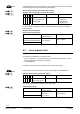

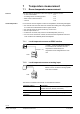
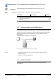
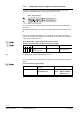
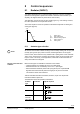
Table Of Contents
- RXB (KNX) applications library
- CLC and RAD description of functions for CC-02
- Table of contents
- 1 Introduction
- 2 Definitions / Tools
- 3 Select communications mode
- 4 Applications / Parameters
- 5 Room operating modes
- 5.1 Description
- 5.2 Overview
- 5.3 Determine the room operating mode with DESIGO (S-mode)
- 5.3.1 Local control of room operating mode via a window contact
- 5.3.2 Central control of room operating mode via input from the Use schedule
- 5.3.3 Central and local control of room operating modebased on occupancy
- 5.3.4 Central control of room operating mode via room operating mode schedule
- 5.3.5 Local control of room operating mode with a room unit
- 5.3.6 Local control of room operating mode via the Temporary Comfort mode input
- 5.3.7 Effective room operating mode
- 5.3.8 DESIGO examples
- 5.4 Determine the room operating mode with third-party products (S-mode)
- 5.4.1 Local control of room operating mode via window contact input
- 5.4.2 Central control of room operating mode with an input from the room operating mode schedule
- 5.4.3 Central control of the room operating mode via the schedules Use and Occupancy
- 5.4.4 Central and local control of room operating mode based on occupancy
- 5.4.5 Local control of room operating mode with a room unit
- 5.4.6 Local control of room operating mode via the Temporary Comfort mode input
- 5.4.7 Effective room operating mode
- 5.4.8 Third-party (S-mode) examples
- 5.5 Determine the room operating mode with Synco (LTE mode)
- 5.5.1 Local control of room operating mode via window contact input
- 5.5.2 Central room operating mode control via Enable Comfort
- 5.5.3 Central control of room operating mode via room operating mode input
- 5.5.4 Local control of room operating mode via presence detector
- 5.5.5 Local control of room operating mode with a room unit
- 5.5.6 LTE mode examples
- 5.6 Determine the room operating mode without a bus (stand-alone)
- 6 Setpoint calculation
- 7 Temperature measurement
- 8 Control sequences
- 9 Master/slave
- 10 General / central functions
- 10.1 Send heartbeat and Receive timeout
- 10.2 Digital inputs
- 10.3 Temporary Comfort mode
- 10.4 Presence detector switch-on and switch-off delay
- 10.5 Heating and cooling demand
- 10.6 Heating/cooling signal output
- 10.7 Special functions
- 10.8 Morning boost (Morning Warmup, 2)
- 10.9 Precooling (Precool, 5)
- 10.10 Test mode (Test, 7)
- 10.11 Emergency heat (8)
- 10.12 Free cooling (Freecool, 10)
- 10.13 Alarm
- 10.14 Reset setpoint shift
- 10.15 Free inputs/outputs
- 10.16 Software version
- 10.17 Device state
- 11 Room unit
- 12 KNX information
- 12.1 Reset and startup response
- 12.2 LED flashing pattern
- 12.3 Startup delay
- 12.4 Bus load
- 12.5 S-mode communication objects for RAD/CLC
- 12.6 LTE-mode communication objects
- 12.7 HandyTool parameters by number
- 12.8 HandyTool parameters, alphabetical
- 12.9 HandyTool enumerations
- 12.10 Data point type description
- 13 FAQ
- 14 Integration of RXB in DESIGO/Synco
- 14.1 Case 1: Integration in Synco
- 14.2 Case 2: Integration in DESIGO
- 14.3 Case 3: Display in DESIGO, with shared Synco schedule
- 14.4 Case 4: Display in DESIGO/Synco, with shared Synco schedule
- 14.5 Case 5: Display in DESIGO, separate schedules
- 14.6 Case 6: Separate display, separate schedules
- 14.7 Case 7: Separate display, shared Synco schedule
- 15 Working with different tools

79/140
Siemens RXB (KNX) Applications library CLC and RAD description of functions for CC-02 CM110384en_04
Building Technologies Control sequences 21 Sep 2010
8 Control sequences
8.1 Radiator (RAD01)
The radiator application has a continuous heating sequence. The room controllers
operate with a PI algorithm optimized for thermal or motorized valve actuators. (For
simplicity, the diagram below only shows the P-control action.)
This application can also be used for other heating types, e.g. floor heating. However,
the control parameters are not optimized for this.
The control sequences come into operation at the effective setpoints for heating and
cooling (see page 67).
100
0
TR [°C]
Y [%]
SpH
YH
H
Y Output signal
TR Room temperature
SpH Effective heating setpoint
H Heating sequence
YH Heating valve
8.1.1 Actuator type selection
All actuators have threads suitable for fitting to both normally-closed (push to open) and
normally-open (pull-to-open) valves. However, the RX applications do not support
inverse control, which means that only actuators with a pulling action can be used with
"pull-to-open" valves and only actuators with a pushing action can be used with "push-
to-open" valves. This is why, in RX applications, valves with mounted actuators are
always closed when de-energized.
Different valve types are available for selection for the radiator:
– Thermal actuators are controlled by an AC 24 V PDM signal.
– Motorized actuators are controlled by an AC 24 V 3- point signal.
– Electromechanical actuators (motors with spring return) have a special PDM
algorithm that ensures that 50 position changes per day are not exceeded.
This causes a slower control behavior.
Thermal and electromechanical actuators, therefore, require one output while
motorized actuators require two.
The table below shows the possible combinations:
Actuator
type
Controller Outputs required
Thermal RXB24.1
Y1
Motorized RXB24.1
M
Y1
Y2
Electro-
mechanic
(ON / OFF)
RXB24.1
Y1
M
STOP
Note!
Directly connected valve
actuators