
Operating Instructions
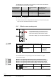
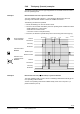
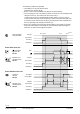
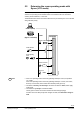
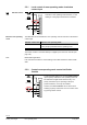
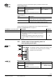
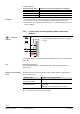
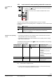
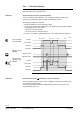
Table Of Contents
- RXB (KNX) applications library
- CLC and RAD description of functions for CC-02
- Table of contents
- 1 Introduction
- 2 Definitions / Tools
- 3 Select communications mode
- 4 Applications / Parameters
- 5 Room operating modes
- 5.1 Description
- 5.2 Overview
- 5.3 Determine the room operating mode with DESIGO (S-mode)
- 5.3.1 Local control of room operating mode via a window contact
- 5.3.2 Central control of room operating mode via input from the Use schedule
- 5.3.3 Central and local control of room operating modebased on occupancy
- 5.3.4 Central control of room operating mode via room operating mode schedule
- 5.3.5 Local control of room operating mode with a room unit
- 5.3.6 Local control of room operating mode via the Temporary Comfort mode input
- 5.3.7 Effective room operating mode
- 5.3.8 DESIGO examples
- 5.4 Determine the room operating mode with third-party products (S-mode)
- 5.4.1 Local control of room operating mode via window contact input
- 5.4.2 Central control of room operating mode with an input from the room operating mode schedule
- 5.4.3 Central control of the room operating mode via the schedules Use and Occupancy
- 5.4.4 Central and local control of room operating mode based on occupancy
- 5.4.5 Local control of room operating mode with a room unit
- 5.4.6 Local control of room operating mode via the Temporary Comfort mode input
- 5.4.7 Effective room operating mode
- 5.4.8 Third-party (S-mode) examples
- 5.5 Determine the room operating mode with Synco (LTE mode)
- 5.5.1 Local control of room operating mode via window contact input
- 5.5.2 Central room operating mode control via Enable Comfort
- 5.5.3 Central control of room operating mode via room operating mode input
- 5.5.4 Local control of room operating mode via presence detector
- 5.5.5 Local control of room operating mode with a room unit
- 5.5.6 LTE mode examples
- 5.6 Determine the room operating mode without a bus (stand-alone)
- 6 Setpoint calculation
- 7 Temperature measurement
- 8 Control sequences
- 9 Master/slave
- 10 General / central functions
- 10.1 Send heartbeat and Receive timeout
- 10.2 Digital inputs
- 10.3 Temporary Comfort mode
- 10.4 Presence detector switch-on and switch-off delay
- 10.5 Heating and cooling demand
- 10.6 Heating/cooling signal output
- 10.7 Special functions
- 10.8 Morning boost (Morning Warmup, 2)
- 10.9 Precooling (Precool, 5)
- 10.10 Test mode (Test, 7)
- 10.11 Emergency heat (8)
- 10.12 Free cooling (Freecool, 10)
- 10.13 Alarm
- 10.14 Reset setpoint shift
- 10.15 Free inputs/outputs
- 10.16 Software version
- 10.17 Device state
- 11 Room unit
- 12 KNX information
- 12.1 Reset and startup response
- 12.2 LED flashing pattern
- 12.3 Startup delay
- 12.4 Bus load
- 12.5 S-mode communication objects for RAD/CLC
- 12.6 LTE-mode communication objects
- 12.7 HandyTool parameters by number
- 12.8 HandyTool parameters, alphabetical
- 12.9 HandyTool enumerations
- 12.10 Data point type description
- 13 FAQ
- 14 Integration of RXB in DESIGO/Synco
- 14.1 Case 1: Integration in Synco
- 14.2 Case 2: Integration in DESIGO
- 14.3 Case 3: Display in DESIGO, with shared Synco schedule
- 14.4 Case 4: Display in DESIGO/Synco, with shared Synco schedule
- 14.5 Case 5: Display in DESIGO, separate schedules
- 14.6 Case 6: Separate display, separate schedules
- 14.7 Case 7: Separate display, shared Synco schedule
- 15 Working with different tools

52/140
Siemens RXB (KNX) Applications library CLC and RAD description of functions for CC-02 CM110384en_04
Building Technologies Room operating modes 21 Sep 2010
The table below shows the effect of the Temporary Comfort mode on the Effective
room operating mode
of the room controller.
Existing Effective
room op. mode
Temporary Comfort
mode
New Effective room
operating mode
Comfort
0 = Not used
No effect.
Precomfort
1 = Trigger
Comfort.
Economy
1 = Trigger
Comfort for Temporary
Comfort period
1)
.
Protection.
1 = Trigger
Protection, unchanged.
Key:
1 means: "changes to 1 ".
1)
Comfort mode is active for the predefined Temporary Comfort period (see page
103). The room controller then returns to
Economy.
5.4.7 Effective room operating mode
PPS2
S
Central Local
1.
3.
S
DI
S
S
DI
3.
Controller
1.
3.
Prio
3.
S
S
The resultant
Effective room operating mode is
available to the building automation and control
system in the following communication objects.
These are for display only and cannot be influenced.
Effective room operating mode (output communication object)
Flags
R W C T U
Type Send heartbeat States
1 0 1 1 0 20.102
DPT_HVACMode
Yes 1 = Comfort
2 = Precomfort
3 = Economy
4 = Protection
The resultant
Effective room operating mode is also available as 4 digital
communication objects:
Effective room operating mode Comfort (output communication object)
Effective room operating mode Precomfort (output communication object)
Effective room operating mode Economy (output communication object)
Effective room operating mode Protection (output communication object)
Flags
R W C T U
Type Send heartbeat States
1 0 1 1 0 1.001
DPT_Switch
Yes 0 = Off
1 = On