
Operating Instructions
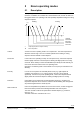
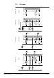
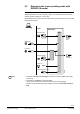
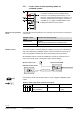
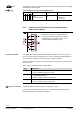
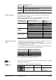
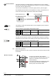
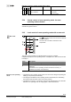
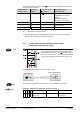
Table Of Contents
- RXB (KNX) applications library
- CLC and RAD description of functions for CC-02
- Table of contents
- 1 Introduction
- 2 Definitions / Tools
- 3 Select communications mode
- 4 Applications / Parameters
- 5 Room operating modes
- 5.1 Description
- 5.2 Overview
- 5.3 Determine the room operating mode with DESIGO (S-mode)
- 5.3.1 Local control of room operating mode via a window contact
- 5.3.2 Central control of room operating mode via input from the Use schedule
- 5.3.3 Central and local control of room operating modebased on occupancy
- 5.3.4 Central control of room operating mode via room operating mode schedule
- 5.3.5 Local control of room operating mode with a room unit
- 5.3.6 Local control of room operating mode via the Temporary Comfort mode input
- 5.3.7 Effective room operating mode
- 5.3.8 DESIGO examples
- 5.4 Determine the room operating mode with third-party products (S-mode)
- 5.4.1 Local control of room operating mode via window contact input
- 5.4.2 Central control of room operating mode with an input from the room operating mode schedule
- 5.4.3 Central control of the room operating mode via the schedules Use and Occupancy
- 5.4.4 Central and local control of room operating mode based on occupancy
- 5.4.5 Local control of room operating mode with a room unit
- 5.4.6 Local control of room operating mode via the Temporary Comfort mode input
- 5.4.7 Effective room operating mode
- 5.4.8 Third-party (S-mode) examples
- 5.5 Determine the room operating mode with Synco (LTE mode)
- 5.5.1 Local control of room operating mode via window contact input
- 5.5.2 Central room operating mode control via Enable Comfort
- 5.5.3 Central control of room operating mode via room operating mode input
- 5.5.4 Local control of room operating mode via presence detector
- 5.5.5 Local control of room operating mode with a room unit
- 5.5.6 LTE mode examples
- 5.6 Determine the room operating mode without a bus (stand-alone)
- 6 Setpoint calculation
- 7 Temperature measurement
- 8 Control sequences
- 9 Master/slave
- 10 General / central functions
- 10.1 Send heartbeat and Receive timeout
- 10.2 Digital inputs
- 10.3 Temporary Comfort mode
- 10.4 Presence detector switch-on and switch-off delay
- 10.5 Heating and cooling demand
- 10.6 Heating/cooling signal output
- 10.7 Special functions
- 10.8 Morning boost (Morning Warmup, 2)
- 10.9 Precooling (Precool, 5)
- 10.10 Test mode (Test, 7)
- 10.11 Emergency heat (8)
- 10.12 Free cooling (Freecool, 10)
- 10.13 Alarm
- 10.14 Reset setpoint shift
- 10.15 Free inputs/outputs
- 10.16 Software version
- 10.17 Device state
- 11 Room unit
- 12 KNX information
- 12.1 Reset and startup response
- 12.2 LED flashing pattern
- 12.3 Startup delay
- 12.4 Bus load
- 12.5 S-mode communication objects for RAD/CLC
- 12.6 LTE-mode communication objects
- 12.7 HandyTool parameters by number
- 12.8 HandyTool parameters, alphabetical
- 12.9 HandyTool enumerations
- 12.10 Data point type description
- 13 FAQ
- 14 Integration of RXB in DESIGO/Synco
- 14.1 Case 1: Integration in Synco
- 14.2 Case 2: Integration in DESIGO
- 14.3 Case 3: Display in DESIGO, with shared Synco schedule
- 14.4 Case 4: Display in DESIGO/Synco, with shared Synco schedule
- 14.5 Case 5: Display in DESIGO, separate schedules
- 14.6 Case 6: Separate display, separate schedules
- 14.7 Case 7: Separate display, shared Synco schedule
- 15 Working with different tools

38/140
Siemens RXB (KNX) Applications library CLC and RAD description of functions for CC-02 CM110384en_04
Building Technologies Room operating modes 21 Sep 2010
The presence detector is connected directly to a digital input on the room controller
(see page 102); alternatively an EIB/KNX presence detector connected to the EIB/KNX
bus may be u
sed (see diagram below).
The two entries are OR-linked; if one of them signals presence, presence applies.
Since EIB/KNX presence detectors are available from a variety of manufacturers, the
name of the S-mode output communication object varies accordingly.
Room controller RXB...
Presence detector input
EIB / KNX presence detector
10385Z07en
Presence detector on DI
OR
Presence detector output
Delay on / off Without delay
The following S-mode communication object is used to integrate a presence detector
connected to the bus:
Presence detector input (output communication object)
Flags
R W C T U
Type Receive timeout States
1 0 1 1 0 1.018
DPT_Occupancy
Yes 0 = Unoccupied
1 = Occupied
The state of the local presence detector on the digital input is mapped in the building
automation and control system via the following S-mode output communication object:
Presence detector output (input communication object)
Flags
R W C T U
Type Send heartbeat States
0 1 1 0 0 1.018
DPT_Occupancy
No 0 = Unoccupied
1 = Occupied
Master/slave applications
Bindings are required in S-mode, in order to transmit the slave presence detector status
to the master.
Effective occupancy
S
Zentral Lokal
1.
2.
3.
S
DI
S
S
S
DI
S
3.
Controller
Prio
PPS2
3.
S
The output communication object
Effective
occupancy
shows the occupancy status of the room
(based on a combination of time schedule and
presence detector).
In the case of integration into a building automation
and control system, the data is mapped to the
following output communication object:
Presence detecto
r
KNX
R
CO
Note