
Operating Instructions
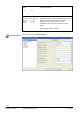
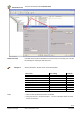
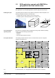
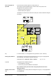
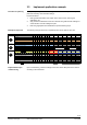
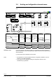
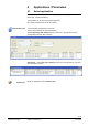
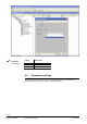
Table Of Contents
- RXB (KNX) applications library
- CLC and RAD description of functions for CC-02
- Table of contents
- 1 Introduction
- 2 Definitions / Tools
- 3 Select communications mode
- 4 Applications / Parameters
- 5 Room operating modes
- 5.1 Description
- 5.2 Overview
- 5.3 Determine the room operating mode with DESIGO (S-mode)
- 5.3.1 Local control of room operating mode via a window contact
- 5.3.2 Central control of room operating mode via input from the Use schedule
- 5.3.3 Central and local control of room operating modebased on occupancy
- 5.3.4 Central control of room operating mode via room operating mode schedule
- 5.3.5 Local control of room operating mode with a room unit
- 5.3.6 Local control of room operating mode via the Temporary Comfort mode input
- 5.3.7 Effective room operating mode
- 5.3.8 DESIGO examples
- 5.4 Determine the room operating mode with third-party products (S-mode)
- 5.4.1 Local control of room operating mode via window contact input
- 5.4.2 Central control of room operating mode with an input from the room operating mode schedule
- 5.4.3 Central control of the room operating mode via the schedules Use and Occupancy
- 5.4.4 Central and local control of room operating mode based on occupancy
- 5.4.5 Local control of room operating mode with a room unit
- 5.4.6 Local control of room operating mode via the Temporary Comfort mode input
- 5.4.7 Effective room operating mode
- 5.4.8 Third-party (S-mode) examples
- 5.5 Determine the room operating mode with Synco (LTE mode)
- 5.5.1 Local control of room operating mode via window contact input
- 5.5.2 Central room operating mode control via Enable Comfort
- 5.5.3 Central control of room operating mode via room operating mode input
- 5.5.4 Local control of room operating mode via presence detector
- 5.5.5 Local control of room operating mode with a room unit
- 5.5.6 LTE mode examples
- 5.6 Determine the room operating mode without a bus (stand-alone)
- 6 Setpoint calculation
- 7 Temperature measurement
- 8 Control sequences
- 9 Master/slave
- 10 General / central functions
- 10.1 Send heartbeat and Receive timeout
- 10.2 Digital inputs
- 10.3 Temporary Comfort mode
- 10.4 Presence detector switch-on and switch-off delay
- 10.5 Heating and cooling demand
- 10.6 Heating/cooling signal output
- 10.7 Special functions
- 10.8 Morning boost (Morning Warmup, 2)
- 10.9 Precooling (Precool, 5)
- 10.10 Test mode (Test, 7)
- 10.11 Emergency heat (8)
- 10.12 Free cooling (Freecool, 10)
- 10.13 Alarm
- 10.14 Reset setpoint shift
- 10.15 Free inputs/outputs
- 10.16 Software version
- 10.17 Device state
- 11 Room unit
- 12 KNX information
- 12.1 Reset and startup response
- 12.2 LED flashing pattern
- 12.3 Startup delay
- 12.4 Bus load
- 12.5 S-mode communication objects for RAD/CLC
- 12.6 LTE-mode communication objects
- 12.7 HandyTool parameters by number
- 12.8 HandyTool parameters, alphabetical
- 12.9 HandyTool enumerations
- 12.10 Data point type description
- 13 FAQ
- 14 Integration of RXB in DESIGO/Synco
- 14.1 Case 1: Integration in Synco
- 14.2 Case 2: Integration in DESIGO
- 14.3 Case 3: Display in DESIGO, with shared Synco schedule
- 14.4 Case 4: Display in DESIGO/Synco, with shared Synco schedule
- 14.5 Case 5: Display in DESIGO, separate schedules
- 14.6 Case 6: Separate display, separate schedules
- 14.7 Case 7: Separate display, shared Synco schedule
- 15 Working with different tools

27/140
Siemens RXB (KNX) Applications library CLC and RAD description of functions for CC-02 CM110384en_04
Building Technologies Select communications mode 21 Sep 2010
3.3 Implement application example
The Synco
TM
planning and commissioning protocol C3127 enables you to clearly draw
plant and necessary communication settings.
Proceed as follows:
1. Enter general information such as plan name, device name, device types,
applications, etc..
2. Copy the device addresses for the bus members along with the basic settings for
communication from the building floor plan.
3. Enter the geographical zone addresses as per the defined groups.
The following example shows the completed protocol for the plant of Sport AG:
Possible settings RMU RMH RMK OZW RMB RXB QAW 1 2 3 4 5 6 7
Plant Sport Ltd Sport Ltd Sport Ltd Sport Ltd Sport Ltd Sport Ltd Sport Ltd
Room number 309 307 308 308 308
Device name X X X - X X - Reception Conference Reception Office Office Office Office
Device type
RMU
7..
RMH,
RMZ
RMK
OZW
771...
RMB
795
RXB
....
QAW
740
RMB795 RXB.. RMB795 [2] RXB.. RXB.. RXB.. RXB..
Plant type X X X - X X - B FC03 FC03 FC03 FC03 FC03
KNX-ID (Example ID: 00FD000016D5) X X X X X X X
Area [ 0...15 ] . Line [ 1; 2...15 ] .
Device address [1..253;
255
]
X X X X X X X 0.2.10 0.2.114 0.2.110 0.2.111 0.2.112 0.2.113
Decentral bus power supply [ Off,
On
]XXX-X--Aus
Clock time operation [
Autonomous
, Slave, Master ] X X X X X - - Autonom
Remote setting chlock slave [ No, Yes ] XXXXX- -Nein
Remote reset of fault [
No
, Yes ] X X X - X - - Nein
Geographical zone (Apartment
.Room.Subzone)
(A.R.S) [ 1...126 ].[ 1...63 ]. [1]
X
2
2X X - 10X X.X.1 X 1.1.1 1.1.1 2.1.1 2.1.1 2.2.1 2.3.1 2.4.1
(with own room sensor)
X
1
2X X - - X X X ---- X X X
Time switch operation [
Autonomous
, Slave, Master ]
X
1
2X X - - - -
Time switch slave (apartment
) [ 1...126 ] . 1 . 1
X
1
2X X - - X.1.1 - 1.1.1 2.1.1 2.1.1 2.1.1 2.1.1
Temperature control [ Master, Slave ] - - - - - X - Master Master Master Master Master
* Control strategy [
Caskade
, Constant, Alternating ]
X
4
------
** Combination of room control [
Master
,
Slave external setpoint , Slave internal setpoint ]
-2XX----
Room group (name)
----
10X - - Conference Office
QAW operation zone (apartment
) [ ---,
1
...126 ] . 1 . 1
----
10X - -
Information
Room /
Room group
Basic settings
Room group Conference
A
partment = 1
Room group Office
A
partment = 2
1
2
3
Upon commissioning, enter the settings for the same-name data points in the devices
according to the created list.
Procedure for planning
Example for Sport Ltd.
Implementation upon
commissioning