
Operating Instructions
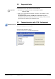
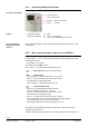
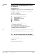
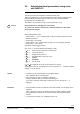
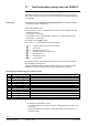

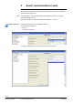
Table Of Contents
- RXB (KNX) applications library
- CLC and RAD description of functions for CC-02
- Table of contents
- 1 Introduction
- 2 Definitions / Tools
- 3 Select communications mode
- 4 Applications / Parameters
- 5 Room operating modes
- 5.1 Description
- 5.2 Overview
- 5.3 Determine the room operating mode with DESIGO (S-mode)
- 5.3.1 Local control of room operating mode via a window contact
- 5.3.2 Central control of room operating mode via input from the Use schedule
- 5.3.3 Central and local control of room operating modebased on occupancy
- 5.3.4 Central control of room operating mode via room operating mode schedule
- 5.3.5 Local control of room operating mode with a room unit
- 5.3.6 Local control of room operating mode via the Temporary Comfort mode input
- 5.3.7 Effective room operating mode
- 5.3.8 DESIGO examples
- 5.4 Determine the room operating mode with third-party products (S-mode)
- 5.4.1 Local control of room operating mode via window contact input
- 5.4.2 Central control of room operating mode with an input from the room operating mode schedule
- 5.4.3 Central control of the room operating mode via the schedules Use and Occupancy
- 5.4.4 Central and local control of room operating mode based on occupancy
- 5.4.5 Local control of room operating mode with a room unit
- 5.4.6 Local control of room operating mode via the Temporary Comfort mode input
- 5.4.7 Effective room operating mode
- 5.4.8 Third-party (S-mode) examples
- 5.5 Determine the room operating mode with Synco (LTE mode)
- 5.5.1 Local control of room operating mode via window contact input
- 5.5.2 Central room operating mode control via Enable Comfort
- 5.5.3 Central control of room operating mode via room operating mode input
- 5.5.4 Local control of room operating mode via presence detector
- 5.5.5 Local control of room operating mode with a room unit
- 5.5.6 LTE mode examples
- 5.6 Determine the room operating mode without a bus (stand-alone)
- 6 Setpoint calculation
- 7 Temperature measurement
- 8 Control sequences
- 9 Master/slave
- 10 General / central functions
- 10.1 Send heartbeat and Receive timeout
- 10.2 Digital inputs
- 10.3 Temporary Comfort mode
- 10.4 Presence detector switch-on and switch-off delay
- 10.5 Heating and cooling demand
- 10.6 Heating/cooling signal output
- 10.7 Special functions
- 10.8 Morning boost (Morning Warmup, 2)
- 10.9 Precooling (Precool, 5)
- 10.10 Test mode (Test, 7)
- 10.11 Emergency heat (8)
- 10.12 Free cooling (Freecool, 10)
- 10.13 Alarm
- 10.14 Reset setpoint shift
- 10.15 Free inputs/outputs
- 10.16 Software version
- 10.17 Device state
- 11 Room unit
- 12 KNX information
- 12.1 Reset and startup response
- 12.2 LED flashing pattern
- 12.3 Startup delay
- 12.4 Bus load
- 12.5 S-mode communication objects for RAD/CLC
- 12.6 LTE-mode communication objects
- 12.7 HandyTool parameters by number
- 12.8 HandyTool parameters, alphabetical
- 12.9 HandyTool enumerations
- 12.10 Data point type description
- 13 FAQ
- 14 Integration of RXB in DESIGO/Synco
- 14.1 Case 1: Integration in Synco
- 14.2 Case 2: Integration in DESIGO
- 14.3 Case 3: Display in DESIGO, with shared Synco schedule
- 14.4 Case 4: Display in DESIGO/Synco, with shared Synco schedule
- 14.5 Case 5: Display in DESIGO, separate schedules
- 14.6 Case 6: Separate display, separate schedules
- 14.7 Case 7: Separate display, shared Synco schedule
- 15 Working with different tools

18/140
Siemens RXB (KNX) Applications library CLC and RAD description of functions for CC-02 CM110384en_04
Building Technologies Definitions / Tools 21 Sep 2010
2.7 Test the periphery using room unit QAX34.3
This function requires a QAX34.3 with index D or higher!
The HandyTool allows you to test the connected field devices (sensors, actuators).
This works only for the controller connected to the HandyTool; master/slave operation
is not possible.
An application must be selected and fully parameterized in the controller (address
and zones can contain default values).
Start parameterization mode:
Press buttons < , > and – simultaneously for about 2 s until the display turns dark.
Release the buttons.
Press button – twice briefly.
Press buttons + and – simultaneously for approx. 2 s The display goes dark.
Press button + twice briefly.
The display now shows
0 (mode 0).
Use + and / or – to choose between the following modes:
0 = Normal mode (normal room unit functions).
1 = Test mode
2 = Display mode (see 2.5.2).
3 = Parameterization mode (see 2.5.2).
4 = Upload (see 2.6).
5 = Download (see 2.6).
6 = Service mode.
The following positions can be selected depending on the type of parameterization.
They are displayed with prefix "T".
The list shows all theoretically possible positions. However, only positions that are
available for selection based on the type of parameterization are displayed.
Theoretically possible positions for periphery testing:
T 01
Sensor input B1
9)
Value of B1 in °C.
T 11
Digital input D1
9)
True state of the contact at D1 (0 = open; 1 = closed).
T 12
Digital input D2
9)
True state of the contact at D2 (0 = open; 1 = closed).
T 21
Heating valve
1)
2)
7)
By considering the configuration (proportional; 100 = 100% pos. signal).
T 22
Cooling valve
1)
2)
7)
By considering the configuration (proportional; 100 = 100% pos. signal).
T 25
Heating surface
1)
4)
7)
By considering the configuration (proportional; 100 = 100% pos. signal).
T 51
Triac Y1
6)
(0 = Triac disabled; 1 = enabled).
T 52
Triac Y2
6)
(0 = Triac disabled; 1 = enabled).
T 53
Triac Y3
6)
(0 = Triac disabled; 1 = enabled).
T 54
Triac Y4
6)
(0 = Triac disabled; 1 = enabled).
1)
Considering the configuration means:
– For thermal actuators, the output is clocked 1:1 during the first 400 s, then as per
the % entry.
– Motorized actuators open at 100% 1.5 times the runtime, and close at 0% 1.5
times the runtime.
Prerequisite