
Operating Instructions
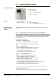
Table Of Contents
- RXB (KNX) applications library
- CLC and RAD description of functions for CC-02
- Table of contents
- 1 Introduction
- 2 Definitions / Tools
- 3 Select communications mode
- 4 Applications / Parameters
- 5 Room operating modes
- 5.1 Description
- 5.2 Overview
- 5.3 Determine the room operating mode with DESIGO (S-mode)
- 5.3.1 Local control of room operating mode via a window contact
- 5.3.2 Central control of room operating mode via input from the Use schedule
- 5.3.3 Central and local control of room operating modebased on occupancy
- 5.3.4 Central control of room operating mode via room operating mode schedule
- 5.3.5 Local control of room operating mode with a room unit
- 5.3.6 Local control of room operating mode via the Temporary Comfort mode input
- 5.3.7 Effective room operating mode
- 5.3.8 DESIGO examples
- 5.4 Determine the room operating mode with third-party products (S-mode)
- 5.4.1 Local control of room operating mode via window contact input
- 5.4.2 Central control of room operating mode with an input from the room operating mode schedule
- 5.4.3 Central control of the room operating mode via the schedules Use and Occupancy
- 5.4.4 Central and local control of room operating mode based on occupancy
- 5.4.5 Local control of room operating mode with a room unit
- 5.4.6 Local control of room operating mode via the Temporary Comfort mode input
- 5.4.7 Effective room operating mode
- 5.4.8 Third-party (S-mode) examples
- 5.5 Determine the room operating mode with Synco (LTE mode)
- 5.5.1 Local control of room operating mode via window contact input
- 5.5.2 Central room operating mode control via Enable Comfort
- 5.5.3 Central control of room operating mode via room operating mode input
- 5.5.4 Local control of room operating mode via presence detector
- 5.5.5 Local control of room operating mode with a room unit
- 5.5.6 LTE mode examples
- 5.6 Determine the room operating mode without a bus (stand-alone)
- 6 Setpoint calculation
- 7 Temperature measurement
- 8 Control sequences
- 9 Master/slave
- 10 General / central functions
- 10.1 Send heartbeat and Receive timeout
- 10.2 Digital inputs
- 10.3 Temporary Comfort mode
- 10.4 Presence detector switch-on and switch-off delay
- 10.5 Heating and cooling demand
- 10.6 Heating/cooling signal output
- 10.7 Special functions
- 10.8 Morning boost (Morning Warmup, 2)
- 10.9 Precooling (Precool, 5)
- 10.10 Test mode (Test, 7)
- 10.11 Emergency heat (8)
- 10.12 Free cooling (Freecool, 10)
- 10.13 Alarm
- 10.14 Reset setpoint shift
- 10.15 Free inputs/outputs
- 10.16 Software version
- 10.17 Device state
- 11 Room unit
- 12 KNX information
- 12.1 Reset and startup response
- 12.2 LED flashing pattern
- 12.3 Startup delay
- 12.4 Bus load
- 12.5 S-mode communication objects for RAD/CLC
- 12.6 LTE-mode communication objects
- 12.7 HandyTool parameters by number
- 12.8 HandyTool parameters, alphabetical
- 12.9 HandyTool enumerations
- 12.10 Data point type description
- 13 FAQ
- 14 Integration of RXB in DESIGO/Synco
- 14.1 Case 1: Integration in Synco
- 14.2 Case 2: Integration in DESIGO
- 14.3 Case 3: Display in DESIGO, with shared Synco schedule
- 14.4 Case 4: Display in DESIGO/Synco, with shared Synco schedule
- 14.5 Case 5: Display in DESIGO, separate schedules
- 14.6 Case 6: Separate display, separate schedules
- 14.7 Case 7: Separate display, shared Synco schedule
- 15 Working with different tools

17/140
Siemens RXB (KNX) Applications library CLC and RAD description of functions for CC-02 CM110384en_04
Building Technologies Definitions / Tools 21 Sep 2010
2.6 Upload/download parameters using room
unit QAX34.3
This function requires a QAX34.3 with index D or higher!
The HandyTool can save 5 different controller parameter sets.
These are uploaded from a fully parameterized controller using the Upload function.
Download allows for transferring such a data set to one or several controllers
(prerequisite: same controller type).
The address, and for LTE the zones, must be adjusted (see 2.5.2).
Do
wnload allows for changing also critical values.
As a worst case scenario, components (controllers/actuators or other plant
parts) may be destroyed.
Start parameterization mode:
Press buttons < , > and – simultaneously for about 2 s until the display turns dark.
Release the buttons.
Press button – twice briefly.
Press buttons + and – simultaneously for approx. 2s The display goes dark.
Press button + twice briefly.
The display now shows
0 (mode 0).
Use + and / or – to choose between the following modes:
0 = Normal mode (normal room unit functions).
1 = Test mode (see 2.7).
2 = Display mode (see 2.5.2).
3 = Parameterization mode (see 2.5.2).
4 = Upload.
5 = Download.
6 = Service mode.
If
4 or 5 is displayed, this mode can be selected via < (Enter).
The storage number (c1) is displayed and can be changed via + / – . Select the desired
storage (1 .. 5) via < (Enter).
If storage is empty, upload begins and the display flashes.
OK is displayed after successful upload.
If the storage is full, "dEL" for "Delete?" is displayed.
Pressing <(Enter) at this time overwrites the existing set.
If you press > (Escape), the storage number which you can change via + / – is
displayed.
If the parameter set does not match the connected controller, error message "Err" is
displayed.
Press > (Escape) to return to the storage number and select a different number.
If the parameter set matches the connected controller, start download (display
flashes).
If connected successfully, "P1" is displayed (see 2.5.2).
STOP
Caution
Upload
Download