
Operating Instructions
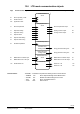
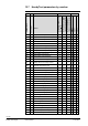
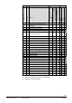
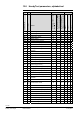
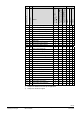
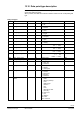
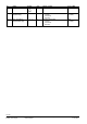
Table Of Contents
- RXB (KNX) applications library
- CLC and RAD description of functions for CC-02
- Table of contents
- 1 Introduction
- 2 Definitions / Tools
- 3 Select communications mode
- 4 Applications / Parameters
- 5 Room operating modes
- 5.1 Description
- 5.2 Overview
- 5.3 Determine the room operating mode with DESIGO (S-mode)
- 5.3.1 Local control of room operating mode via a window contact
- 5.3.2 Central control of room operating mode via input from the Use schedule
- 5.3.3 Central and local control of room operating modebased on occupancy
- 5.3.4 Central control of room operating mode via room operating mode schedule
- 5.3.5 Local control of room operating mode with a room unit
- 5.3.6 Local control of room operating mode via the Temporary Comfort mode input
- 5.3.7 Effective room operating mode
- 5.3.8 DESIGO examples
- 5.4 Determine the room operating mode with third-party products (S-mode)
- 5.4.1 Local control of room operating mode via window contact input
- 5.4.2 Central control of room operating mode with an input from the room operating mode schedule
- 5.4.3 Central control of the room operating mode via the schedules Use and Occupancy
- 5.4.4 Central and local control of room operating mode based on occupancy
- 5.4.5 Local control of room operating mode with a room unit
- 5.4.6 Local control of room operating mode via the Temporary Comfort mode input
- 5.4.7 Effective room operating mode
- 5.4.8 Third-party (S-mode) examples
- 5.5 Determine the room operating mode with Synco (LTE mode)
- 5.5.1 Local control of room operating mode via window contact input
- 5.5.2 Central room operating mode control via Enable Comfort
- 5.5.3 Central control of room operating mode via room operating mode input
- 5.5.4 Local control of room operating mode via presence detector
- 5.5.5 Local control of room operating mode with a room unit
- 5.5.6 LTE mode examples
- 5.6 Determine the room operating mode without a bus (stand-alone)
- 6 Setpoint calculation
- 7 Temperature measurement
- 8 Control sequences
- 9 Master/slave
- 10 General / central functions
- 10.1 Send heartbeat and Receive timeout
- 10.2 Digital inputs
- 10.3 Temporary Comfort mode
- 10.4 Presence detector switch-on and switch-off delay
- 10.5 Heating and cooling demand
- 10.6 Heating/cooling signal output
- 10.7 Special functions
- 10.8 Morning boost (Morning Warmup, 2)
- 10.9 Precooling (Precool, 5)
- 10.10 Test mode (Test, 7)
- 10.11 Emergency heat (8)
- 10.12 Free cooling (Freecool, 10)
- 10.13 Alarm
- 10.14 Reset setpoint shift
- 10.15 Free inputs/outputs
- 10.16 Software version
- 10.17 Device state
- 11 Room unit
- 12 KNX information
- 12.1 Reset and startup response
- 12.2 LED flashing pattern
- 12.3 Startup delay
- 12.4 Bus load
- 12.5 S-mode communication objects for RAD/CLC
- 12.6 LTE-mode communication objects
- 12.7 HandyTool parameters by number
- 12.8 HandyTool parameters, alphabetical
- 12.9 HandyTool enumerations
- 12.10 Data point type description
- 13 FAQ
- 14 Integration of RXB in DESIGO/Synco
- 14.1 Case 1: Integration in Synco
- 14.2 Case 2: Integration in DESIGO
- 14.3 Case 3: Display in DESIGO, with shared Synco schedule
- 14.4 Case 4: Display in DESIGO/Synco, with shared Synco schedule
- 14.5 Case 5: Display in DESIGO, separate schedules
- 14.6 Case 6: Separate display, separate schedules
- 14.7 Case 7: Separate display, shared Synco schedule
- 15 Working with different tools

127/140
Siemens RXB (KNX) Applications library CLC and RAD description of functions for CC-02 CM110384en_04
Building Technologies KNX information 21 Sep 2010
12.10 Data point type description
Instead of the previously referenced EIS data types, this document now references the
new Konnex data point types.
Where possible, the table which follows includes a reference to the corresponding EIS
type.
Data point types
ID Name Format Unit Range / coding Corr. to EIS
1.001 DPT_Switch B
(1)
Bit 0 = OFF
1 = ON
EIS1
1.003 DPT_Enable B
(1)
Bit 0 = Disabled
1 = Enabled
EIS1
1.005 DPT_Alarm B
(1)
Bit 0 = No alarm
1 = Alarm
EIS1
1.017 DPT_Trigger B
(1)
Bit 0 = (not used)
1 = Trigger
EIS1
1.018 DPT_Occupancy B
(1)
Bit 0 = Unoccupied
1 = Occupied
EIS1
1.019 DPT_Window_Door B
(1)
Bit 0 = Closed
1 = Open
EIS1
1.100 DPT_HeatCool B
(1)
Bit 0 = Cooling
1 = Heating
EIS1
5.001 DPT_Scaling U
(8)
% 0...100% 0 = 0%
255 = 100%
EIS6
5.004 DPT_RelPosValve U
(8)
% 0...100% 0 = 0%
255 = 255%
EIS6
6.001 DPT_Percent_V8 V
(8)
% -100%...+100% -100 = -100%
+100 = +100%
(EIS14)
8.010 DPT_Percent_V16 V
(16)
% -100%...+100% -10000 = -100%
0 = 0%
+10000 = +100%
EIS10
9.001 DPT_Value_Temp F
(16)
°C Floating point EIS5
9.002 DPT_Value_Tempd F
(16)
K Floating point EIS5
20.002 DPT_BuildingMode N
(8)
Enum. 0 = Used
1 = Not in use
2 = Protection
(EIS14)
20.003 DPT_OccMode N
(8)
Enum. 0 = Occupied
1 = Standby
2 = Unoccupied
(EIS14)
20.102 DPT_HVACMode N
(8)
Enum. 0 = Auto
1 = Comfort
2 = Precomfort
3 = Economy
4 = Protection
(EIS14)
20.105 DPT_HVACContr
Mode
N
(8)
Enum. 0 = Auto
1 = Heat
2 = Morning Warmup
3 = Cool
4 = Night Purge
5 = Precool
6 = Off
7 = Test
8 = Emergency Heat
9 = Fan only
10 = Free Cool
11 = Ice
20 = NoDem
255 = NUL
Other: reserved
(EIS14)