
Operating Instructions
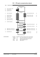
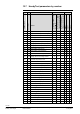
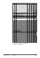
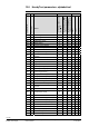
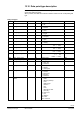
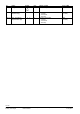
Table Of Contents
- RXB (KNX) applications library
- CLC and RAD description of functions for CC-02
- Table of contents
- 1 Introduction
- 2 Definitions / Tools
- 3 Select communications mode
- 4 Applications / Parameters
- 5 Room operating modes
- 5.1 Description
- 5.2 Overview
- 5.3 Determine the room operating mode with DESIGO (S-mode)
- 5.3.1 Local control of room operating mode via a window contact
- 5.3.2 Central control of room operating mode via input from the Use schedule
- 5.3.3 Central and local control of room operating modebased on occupancy
- 5.3.4 Central control of room operating mode via room operating mode schedule
- 5.3.5 Local control of room operating mode with a room unit
- 5.3.6 Local control of room operating mode via the Temporary Comfort mode input
- 5.3.7 Effective room operating mode
- 5.3.8 DESIGO examples
- 5.4 Determine the room operating mode with third-party products (S-mode)
- 5.4.1 Local control of room operating mode via window contact input
- 5.4.2 Central control of room operating mode with an input from the room operating mode schedule
- 5.4.3 Central control of the room operating mode via the schedules Use and Occupancy
- 5.4.4 Central and local control of room operating mode based on occupancy
- 5.4.5 Local control of room operating mode with a room unit
- 5.4.6 Local control of room operating mode via the Temporary Comfort mode input
- 5.4.7 Effective room operating mode
- 5.4.8 Third-party (S-mode) examples
- 5.5 Determine the room operating mode with Synco (LTE mode)
- 5.5.1 Local control of room operating mode via window contact input
- 5.5.2 Central room operating mode control via Enable Comfort
- 5.5.3 Central control of room operating mode via room operating mode input
- 5.5.4 Local control of room operating mode via presence detector
- 5.5.5 Local control of room operating mode with a room unit
- 5.5.6 LTE mode examples
- 5.6 Determine the room operating mode without a bus (stand-alone)
- 6 Setpoint calculation
- 7 Temperature measurement
- 8 Control sequences
- 9 Master/slave
- 10 General / central functions
- 10.1 Send heartbeat and Receive timeout
- 10.2 Digital inputs
- 10.3 Temporary Comfort mode
- 10.4 Presence detector switch-on and switch-off delay
- 10.5 Heating and cooling demand
- 10.6 Heating/cooling signal output
- 10.7 Special functions
- 10.8 Morning boost (Morning Warmup, 2)
- 10.9 Precooling (Precool, 5)
- 10.10 Test mode (Test, 7)
- 10.11 Emergency heat (8)
- 10.12 Free cooling (Freecool, 10)
- 10.13 Alarm
- 10.14 Reset setpoint shift
- 10.15 Free inputs/outputs
- 10.16 Software version
- 10.17 Device state
- 11 Room unit
- 12 KNX information
- 12.1 Reset and startup response
- 12.2 LED flashing pattern
- 12.3 Startup delay
- 12.4 Bus load
- 12.5 S-mode communication objects for RAD/CLC
- 12.6 LTE-mode communication objects
- 12.7 HandyTool parameters by number
- 12.8 HandyTool parameters, alphabetical
- 12.9 HandyTool enumerations
- 12.10 Data point type description
- 13 FAQ
- 14 Integration of RXB in DESIGO/Synco
- 14.1 Case 1: Integration in Synco
- 14.2 Case 2: Integration in DESIGO
- 14.3 Case 3: Display in DESIGO, with shared Synco schedule
- 14.4 Case 4: Display in DESIGO/Synco, with shared Synco schedule
- 14.5 Case 5: Display in DESIGO, separate schedules
- 14.6 Case 6: Separate display, separate schedules
- 14.7 Case 7: Separate display, shared Synco schedule
- 15 Working with different tools

126/140
Siemens RXB (KNX) Applications library CLC and RAD description of functions for CC-02 CM110384en_04
Building Technologies KNX information 21 Sep 2010
12.9 HandyTool enumerations
No. Parameter
CLC / RAD
FNC
1 - 3 Physical address X X
5 Plant type X X
FC-10 FC-11 FC-12 CC-02
6 Communications mode. X X
0 = S-Mode 1 = FNC02 1 = FNC10 1 = FNC03 1 = CLC01
8 - 10 Geographical zone X X
1 = S+LTE-M 2 = FNC04 2 = FNC12 2 = FNC05 2 = CLC02
11 -13 Time switch zone X X
3 = FNC08 3 = FNC18 3 = RAD01
14 Heat distribution zone air heater. X
4 = FNC20
15 Refrig distribution zone air cooler. X
16 Heat distr zone heating surface X X
17 Refrig distr zone cooling surface X
18 Outside temperature zone X X
21 Master/slave. X X
0 = Slave
22 - 24 Master/slave zone X X
1 = Master
30 - 37 Setpoints X X
C: Prot / Eco / Pre-C / Comf H: Comf / Pre-C / Eco / Prot
38 Minimum supply air temperature X
39 Maximum supply air temperature X
40 Risk of frost limit X
50 Control sequence X
0 = c/o / 1 = Cooling / 2 = Heating
51
Actuator type cool surf valve
X
VA VA = Valve actuators:
52
Running time cool surface valve
X
54
Offset cooling surface valve
X
1 = on/off 1 = STE71 10 = SSA81 250 = Mot BUS
56 Electric heater X
254 = continuous 3 = STA71 11 = SSB81 252 = El-mech 3rd
57 Power consumption el heater X
4 = STP71 12 = SQS81 253 = Therm. 3rd
60 Actuator type H/C coil valve X
VA 5 = STA72E 13 = SSC81 254 = Mot. 3rd
61 Running time damper heating X
6 = STP72E 14 = SSP 81
62 Running time damper cooling X
63 Actuator type heat surf valve X X
VA
64 Running time heat surface valve X X
66
Offset heating surface valve
XX
70 Changeover time damper X
71
Offset heating valve
X
72
Offset cooling valve
X
73 Outside temp min damper pos X
74 Running time outside air damper X
75 Minimum damper position X
78 Outside temp 0% valve pos X X
79 Outside temp max valve pos X X
80 Max valve position X
85 Heating (coil) outp bus valve X
86 Heating surface output bus valve actuator X
0 = OFF
87 Cooling (coil) outp bus valve X
1 = ON
88 Cooling surface outp bus valve, X
89 Heating outp bus el heating X
92 Temperature sensor. X X
0 = Ret. air / 1 = Room / 3 = Meas. val. / 255 = No sensor
93 Fan control X
0 = manual / 1 = automatic
94 Fan speeds X
0 = automatic / 1 = 1-stage / 2 = 2-stage / 3 = 3-stage
95 Minimum on time X
96 Periodic fan kick Comfort X
97 Periodic fan kick Eco X
98 Fan overrun time X
101 Measured value correction X X
103 Setpoint offset range X X
105 Local Comfort mode X X
0 = disabled / 1 = enabled
108 Temperature unit X X
0 = °F / 1 = °C
109 Standard display X X
2 = Room temp. / 48 = Setpoint / 96 = No display
110 Setpoint display X X
0 = relative / 4 = absolute
113 Digital input 1 X X
0 = BUS 1 / Contact closed 8 = Dewpt. / Contact closed
114 Digital input 2 X X
1 = BUS 1 / Contact open 9 = Dewpt. / Contact open
117 Temporary Comfort mode X X
2 = Occup / Contact closed 16 = Overt. / Contact open
119 On-delay occupancy detector X X
3 = Occup / Contact open 17 = Overt. / Contact closed
120 Off-delay occupancy detector X X
4 = Wind. open / Contact open 32 = Frost / Contact closed
127 Send heartbeat X X
5 = Wind. open / Contact closed 33 = Frost / Contact open
128 Receive timeout X X
131 Heat demand signal X X
132 Cooling demand signal X X
0 = OFF
134 Boost heating X X
1 = ON
135 Preecooling / Free cooling X X
136 Rapid ventilation (earlier: air purge) X
137
Reset setpoint offset X X
138 Night purge X
236
Application set
XX
237
Application version
XX
238
Operating system version
XX
239
KNX interface version
XX
240
Device state
XX
.
.
.
.
.