
Operating Instructions
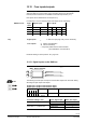
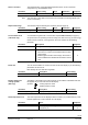
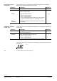
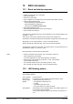
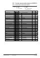
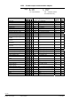
Table Of Contents
- RXB (KNX) applications library
- CLC and RAD description of functions for CC-02
- Table of contents
- 1 Introduction
- 2 Definitions / Tools
- 3 Select communications mode
- 4 Applications / Parameters
- 5 Room operating modes
- 5.1 Description
- 5.2 Overview
- 5.3 Determine the room operating mode with DESIGO (S-mode)
- 5.3.1 Local control of room operating mode via a window contact
- 5.3.2 Central control of room operating mode via input from the Use schedule
- 5.3.3 Central and local control of room operating modebased on occupancy
- 5.3.4 Central control of room operating mode via room operating mode schedule
- 5.3.5 Local control of room operating mode with a room unit
- 5.3.6 Local control of room operating mode via the Temporary Comfort mode input
- 5.3.7 Effective room operating mode
- 5.3.8 DESIGO examples
- 5.4 Determine the room operating mode with third-party products (S-mode)
- 5.4.1 Local control of room operating mode via window contact input
- 5.4.2 Central control of room operating mode with an input from the room operating mode schedule
- 5.4.3 Central control of the room operating mode via the schedules Use and Occupancy
- 5.4.4 Central and local control of room operating mode based on occupancy
- 5.4.5 Local control of room operating mode with a room unit
- 5.4.6 Local control of room operating mode via the Temporary Comfort mode input
- 5.4.7 Effective room operating mode
- 5.4.8 Third-party (S-mode) examples
- 5.5 Determine the room operating mode with Synco (LTE mode)
- 5.5.1 Local control of room operating mode via window contact input
- 5.5.2 Central room operating mode control via Enable Comfort
- 5.5.3 Central control of room operating mode via room operating mode input
- 5.5.4 Local control of room operating mode via presence detector
- 5.5.5 Local control of room operating mode with a room unit
- 5.5.6 LTE mode examples
- 5.6 Determine the room operating mode without a bus (stand-alone)
- 6 Setpoint calculation
- 7 Temperature measurement
- 8 Control sequences
- 9 Master/slave
- 10 General / central functions
- 10.1 Send heartbeat and Receive timeout
- 10.2 Digital inputs
- 10.3 Temporary Comfort mode
- 10.4 Presence detector switch-on and switch-off delay
- 10.5 Heating and cooling demand
- 10.6 Heating/cooling signal output
- 10.7 Special functions
- 10.8 Morning boost (Morning Warmup, 2)
- 10.9 Precooling (Precool, 5)
- 10.10 Test mode (Test, 7)
- 10.11 Emergency heat (8)
- 10.12 Free cooling (Freecool, 10)
- 10.13 Alarm
- 10.14 Reset setpoint shift
- 10.15 Free inputs/outputs
- 10.16 Software version
- 10.17 Device state
- 11 Room unit
- 12 KNX information
- 12.1 Reset and startup response
- 12.2 LED flashing pattern
- 12.3 Startup delay
- 12.4 Bus load
- 12.5 S-mode communication objects for RAD/CLC
- 12.6 LTE-mode communication objects
- 12.7 HandyTool parameters by number
- 12.8 HandyTool parameters, alphabetical
- 12.9 HandyTool enumerations
- 12.10 Data point type description
- 13 FAQ
- 14 Integration of RXB in DESIGO/Synco
- 14.1 Case 1: Integration in Synco
- 14.2 Case 2: Integration in DESIGO
- 14.3 Case 3: Display in DESIGO, with shared Synco schedule
- 14.4 Case 4: Display in DESIGO/Synco, with shared Synco schedule
- 14.5 Case 5: Display in DESIGO, separate schedules
- 14.6 Case 6: Separate display, separate schedules
- 14.7 Case 7: Separate display, shared Synco schedule
- 15 Working with different tools

117/140
Siemens RXB (KNX) Applications library CLC and RAD description of functions for CC-02 CM110384en_04
Building Technologies KNX information 21 Sep 2010
12 KNX information
12.1 Reset and startup response
A reset is initiated under the following circumstances:
Failure of the processor (e.g. watchdog).
After a power failure.
After a bus power failure.
Upon completion of a self test (using communication object Status request).
Via ETS (without startup delay)
– After downloading the physical address
– After downloading the parameters
– Via ETS (menu
Commissioning, Reset).
After parameterization in ACS.
After exiting Parameterization mode in the HandyTool.
After Test with the HandyTool
The application is restarted after every reset. Depending on the controller address, this
may take 1 ... 255 s.
Then, the bus connection is opened and all connected valve actuators are
synchronized. This takes the following time depending on application and actuator type:
Typically 170 s for closing (runtime + 10%) for motorized actuators.
300 s ON and 300 s OFF (3rd party: 400 + 400 s) for thermal actuators.
The application is placed in a safe state. Any outputs that are not synchronized are not
operated (triac outputs = 0, and relay = open).
Normal operation is resumed after synchronization.
When the controller exits test mode, only a soft reset is carried out:
– Valve actuators are synchronized.
– The control algorithm but not the entire application is restarted.
Each time the control sequence reaches 0% or 100%, a limit position
synchronization takes place.
– For motorized actuators close or open during (runtime + 10%).
– 300 s ON and 300 s OFF (3rd party: 400 s) for thermal actuators.
12.2 LED flashing pattern
An LED is located at the controller's bottom right indicating the operating state by
various flashing patterns:
Green, flashing Normal operation.
Red, flashing Programming mode for address assignment (ETS3 / ACS).
Orange / green,
flashing
Startup phase (see above 12.1).
No application selected (see 4.1).
Loading.
– Download from ETS3 or ACS.
– Room unit QAX34.3 in HandyTool mode.
Other patterns After switching on the operating voltage, the controller flashes for 3
to 5 seconds in different patterns.
If other patterns appear during normal operation, this indicates an
error.
Notes