
Operating Instructions
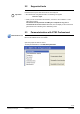
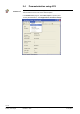
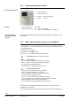
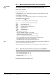
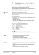

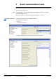
Table Of Contents
- RXB (KNX) applications library
- CLC and RAD description of functions for CC-02
- Table of contents
- 1 Introduction
- 2 Definitions / Tools
- 3 Select communications mode
- 4 Applications / Parameters
- 5 Room operating modes
- 5.1 Description
- 5.2 Overview
- 5.3 Determine the room operating mode with DESIGO (S-mode)
- 5.3.1 Local control of room operating mode via a window contact
- 5.3.2 Central control of room operating mode via input from the Use schedule
- 5.3.3 Central and local control of room operating modebased on occupancy
- 5.3.4 Central control of room operating mode via room operating mode schedule
- 5.3.5 Local control of room operating mode with a room unit
- 5.3.6 Local control of room operating mode via the Temporary Comfort mode input
- 5.3.7 Effective room operating mode
- 5.3.8 DESIGO examples
- 5.4 Determine the room operating mode with third-party products (S-mode)
- 5.4.1 Local control of room operating mode via window contact input
- 5.4.2 Central control of room operating mode with an input from the room operating mode schedule
- 5.4.3 Central control of the room operating mode via the schedules Use and Occupancy
- 5.4.4 Central and local control of room operating mode based on occupancy
- 5.4.5 Local control of room operating mode with a room unit
- 5.4.6 Local control of room operating mode via the Temporary Comfort mode input
- 5.4.7 Effective room operating mode
- 5.4.8 Third-party (S-mode) examples
- 5.5 Determine the room operating mode with Synco (LTE mode)
- 5.5.1 Local control of room operating mode via window contact input
- 5.5.2 Central room operating mode control via Enable Comfort
- 5.5.3 Central control of room operating mode via room operating mode input
- 5.5.4 Local control of room operating mode via presence detector
- 5.5.5 Local control of room operating mode with a room unit
- 5.5.6 LTE mode examples
- 5.6 Determine the room operating mode without a bus (stand-alone)
- 6 Setpoint calculation
- 7 Temperature measurement
- 8 Control sequences
- 9 Master/slave
- 10 General / central functions
- 10.1 Send heartbeat and Receive timeout
- 10.2 Digital inputs
- 10.3 Temporary Comfort mode
- 10.4 Presence detector switch-on and switch-off delay
- 10.5 Heating and cooling demand
- 10.6 Heating/cooling signal output
- 10.7 Special functions
- 10.8 Morning boost (Morning Warmup, 2)
- 10.9 Precooling (Precool, 5)
- 10.10 Test mode (Test, 7)
- 10.11 Emergency heat (8)
- 10.12 Free cooling (Freecool, 10)
- 10.13 Alarm
- 10.14 Reset setpoint shift
- 10.15 Free inputs/outputs
- 10.16 Software version
- 10.17 Device state
- 11 Room unit
- 12 KNX information
- 12.1 Reset and startup response
- 12.2 LED flashing pattern
- 12.3 Startup delay
- 12.4 Bus load
- 12.5 S-mode communication objects for RAD/CLC
- 12.6 LTE-mode communication objects
- 12.7 HandyTool parameters by number
- 12.8 HandyTool parameters, alphabetical
- 12.9 HandyTool enumerations
- 12.10 Data point type description
- 13 FAQ
- 14 Integration of RXB in DESIGO/Synco
- 14.1 Case 1: Integration in Synco
- 14.2 Case 2: Integration in DESIGO
- 14.3 Case 3: Display in DESIGO, with shared Synco schedule
- 14.4 Case 4: Display in DESIGO/Synco, with shared Synco schedule
- 14.5 Case 5: Display in DESIGO, separate schedules
- 14.6 Case 6: Separate display, separate schedules
- 14.7 Case 7: Separate display, shared Synco schedule
- 15 Working with different tools

11/140
Siemens RXB (KNX) Applications library CLC and RAD description of functions for CC-02 CM110384en_04
Building Technologies Definitions / Tools 21 Sep 2010
2.2 Supported tools
The RXB Konnex controllers can be commissioned either with the Konnex tool ETS3
Professional, the Synco ACS Service too or the HandyTool.
Be careful when using different tools. The following rule applies:
Last one's right!
When you use an OCI700 as the interface, connect it to the controller's or room
unit's service socket.
The OCI700 must be powered via USB by the computer as long as it is
connected to the service socket. Otherwise, the LCD display for the room device
goes dark and the controller goes to addressing mode.
2.3 Parameterization with ETS3 Professional
This manual does not describe how physical addresses are defined.
Refer to the EIB manual for more details.
Open the project and select a device.
To start parameterization, select Edit, Edit parameters.
STOP
Important!
ETS3 Professional