
Operating Instructions
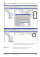
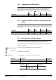
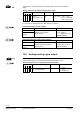
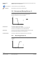
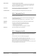
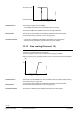
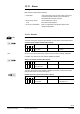
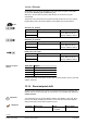
Table Of Contents
- RXB (KNX) applications library
- CLC and RAD description of functions for CC-02
- Table of contents
- 1 Introduction
- 2 Definitions / Tools
- 3 Select communications mode
- 4 Applications / Parameters
- 5 Room operating modes
- 5.1 Description
- 5.2 Overview
- 5.3 Determine the room operating mode with DESIGO (S-mode)
- 5.3.1 Local control of room operating mode via a window contact
- 5.3.2 Central control of room operating mode via input from the Use schedule
- 5.3.3 Central and local control of room operating modebased on occupancy
- 5.3.4 Central control of room operating mode via room operating mode schedule
- 5.3.5 Local control of room operating mode with a room unit
- 5.3.6 Local control of room operating mode via the Temporary Comfort mode input
- 5.3.7 Effective room operating mode
- 5.3.8 DESIGO examples
- 5.4 Determine the room operating mode with third-party products (S-mode)
- 5.4.1 Local control of room operating mode via window contact input
- 5.4.2 Central control of room operating mode with an input from the room operating mode schedule
- 5.4.3 Central control of the room operating mode via the schedules Use and Occupancy
- 5.4.4 Central and local control of room operating mode based on occupancy
- 5.4.5 Local control of room operating mode with a room unit
- 5.4.6 Local control of room operating mode via the Temporary Comfort mode input
- 5.4.7 Effective room operating mode
- 5.4.8 Third-party (S-mode) examples
- 5.5 Determine the room operating mode with Synco (LTE mode)
- 5.5.1 Local control of room operating mode via window contact input
- 5.5.2 Central room operating mode control via Enable Comfort
- 5.5.3 Central control of room operating mode via room operating mode input
- 5.5.4 Local control of room operating mode via presence detector
- 5.5.5 Local control of room operating mode with a room unit
- 5.5.6 LTE mode examples
- 5.6 Determine the room operating mode without a bus (stand-alone)
- 6 Setpoint calculation
- 7 Temperature measurement
- 8 Control sequences
- 9 Master/slave
- 10 General / central functions
- 10.1 Send heartbeat and Receive timeout
- 10.2 Digital inputs
- 10.3 Temporary Comfort mode
- 10.4 Presence detector switch-on and switch-off delay
- 10.5 Heating and cooling demand
- 10.6 Heating/cooling signal output
- 10.7 Special functions
- 10.8 Morning boost (Morning Warmup, 2)
- 10.9 Precooling (Precool, 5)
- 10.10 Test mode (Test, 7)
- 10.11 Emergency heat (8)
- 10.12 Free cooling (Freecool, 10)
- 10.13 Alarm
- 10.14 Reset setpoint shift
- 10.15 Free inputs/outputs
- 10.16 Software version
- 10.17 Device state
- 11 Room unit
- 12 KNX information
- 12.1 Reset and startup response
- 12.2 LED flashing pattern
- 12.3 Startup delay
- 12.4 Bus load
- 12.5 S-mode communication objects for RAD/CLC
- 12.6 LTE-mode communication objects
- 12.7 HandyTool parameters by number
- 12.8 HandyTool parameters, alphabetical
- 12.9 HandyTool enumerations
- 12.10 Data point type description
- 13 FAQ
- 14 Integration of RXB in DESIGO/Synco
- 14.1 Case 1: Integration in Synco
- 14.2 Case 2: Integration in DESIGO
- 14.3 Case 3: Display in DESIGO, with shared Synco schedule
- 14.4 Case 4: Display in DESIGO/Synco, with shared Synco schedule
- 14.5 Case 5: Display in DESIGO, separate schedules
- 14.6 Case 6: Separate display, separate schedules
- 14.7 Case 7: Separate display, shared Synco schedule
- 15 Working with different tools

109/140
Siemens RXB (KNX) Applications library CLC and RAD description of functions for CC-02 CM110384en_04
Building Technologies General / central functions 21 Sep 2010
10.13 Alarm
Alarming works differently in S-mode and LTE mode.
RXB controller support different alarms:
PPS2 fault If the connection to the room unit is faulty at the room
controller (via PPS2 interface), the information is
transmitted with this alarm message.
Room temp. sensor
error
Sensor interruption or short.
No valid room temperature.
Room air condensation Risk of condensation if temperature drops below
dewpoint temperature.
10.13.1 S-mode
In S-mode, the above alarms are summarized and provided as common alarm.
The alarm message is mapped to the following S-mode output communication object:
Common alarm (output communication object)
Flags
R W C T U
Type Send heartbeat States
1 0 1 1 0 1.005
DPT_Alarm
Yes 0 = No alarm
1 = Alarm
As soon as the cause of the alarm ceases to exist, the alarm message disappears.
In addition, the output
Alarm info provides detailed information:
Alarm info (output communication object)
Flags
R W C T U
Type Send heartbeat Info
1 0 1 1 0 219.001
DPT_AlarmInfo
Yes See Konnex specification
The
Alarm info output can be enabled or disabled via another communication object
(this also affects the LTE mode fault signal):
Enable alarm info (input communication object)
Flags
R W C T U
Type Receive timeout States
0 1 1 0 0 1.003
DPT_Enable
Yes (fixed 42 hours) 0 = Disabled / Off
1 = Enabled / On
KNX
R
CO
Note