
Operating Instructions
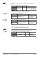
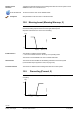
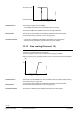
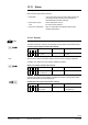
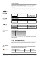
Table Of Contents
- RXB (KNX) applications library
- CLC and RAD description of functions for CC-02
- Table of contents
- 1 Introduction
- 2 Definitions / Tools
- 3 Select communications mode
- 4 Applications / Parameters
- 5 Room operating modes
- 5.1 Description
- 5.2 Overview
- 5.3 Determine the room operating mode with DESIGO (S-mode)
- 5.3.1 Local control of room operating mode via a window contact
- 5.3.2 Central control of room operating mode via input from the Use schedule
- 5.3.3 Central and local control of room operating modebased on occupancy
- 5.3.4 Central control of room operating mode via room operating mode schedule
- 5.3.5 Local control of room operating mode with a room unit
- 5.3.6 Local control of room operating mode via the Temporary Comfort mode input
- 5.3.7 Effective room operating mode
- 5.3.8 DESIGO examples
- 5.4 Determine the room operating mode with third-party products (S-mode)
- 5.4.1 Local control of room operating mode via window contact input
- 5.4.2 Central control of room operating mode with an input from the room operating mode schedule
- 5.4.3 Central control of the room operating mode via the schedules Use and Occupancy
- 5.4.4 Central and local control of room operating mode based on occupancy
- 5.4.5 Local control of room operating mode with a room unit
- 5.4.6 Local control of room operating mode via the Temporary Comfort mode input
- 5.4.7 Effective room operating mode
- 5.4.8 Third-party (S-mode) examples
- 5.5 Determine the room operating mode with Synco (LTE mode)
- 5.5.1 Local control of room operating mode via window contact input
- 5.5.2 Central room operating mode control via Enable Comfort
- 5.5.3 Central control of room operating mode via room operating mode input
- 5.5.4 Local control of room operating mode via presence detector
- 5.5.5 Local control of room operating mode with a room unit
- 5.5.6 LTE mode examples
- 5.6 Determine the room operating mode without a bus (stand-alone)
- 6 Setpoint calculation
- 7 Temperature measurement
- 8 Control sequences
- 9 Master/slave
- 10 General / central functions
- 10.1 Send heartbeat and Receive timeout
- 10.2 Digital inputs
- 10.3 Temporary Comfort mode
- 10.4 Presence detector switch-on and switch-off delay
- 10.5 Heating and cooling demand
- 10.6 Heating/cooling signal output
- 10.7 Special functions
- 10.8 Morning boost (Morning Warmup, 2)
- 10.9 Precooling (Precool, 5)
- 10.10 Test mode (Test, 7)
- 10.11 Emergency heat (8)
- 10.12 Free cooling (Freecool, 10)
- 10.13 Alarm
- 10.14 Reset setpoint shift
- 10.15 Free inputs/outputs
- 10.16 Software version
- 10.17 Device state
- 11 Room unit
- 12 KNX information
- 12.1 Reset and startup response
- 12.2 LED flashing pattern
- 12.3 Startup delay
- 12.4 Bus load
- 12.5 S-mode communication objects for RAD/CLC
- 12.6 LTE-mode communication objects
- 12.7 HandyTool parameters by number
- 12.8 HandyTool parameters, alphabetical
- 12.9 HandyTool enumerations
- 12.10 Data point type description
- 13 FAQ
- 14 Integration of RXB in DESIGO/Synco
- 14.1 Case 1: Integration in Synco
- 14.2 Case 2: Integration in DESIGO
- 14.3 Case 3: Display in DESIGO, with shared Synco schedule
- 14.4 Case 4: Display in DESIGO/Synco, with shared Synco schedule
- 14.5 Case 5: Display in DESIGO, separate schedules
- 14.6 Case 6: Separate display, separate schedules
- 14.7 Case 7: Separate display, shared Synco schedule
- 15 Working with different tools

105/140
Siemens RXB (KNX) Applications library CLC and RAD description of functions for CC-02 CM110384en_04
Building Technologies General / central functions 21 Sep 2010
10.7 Special functions
The functions described in sections 10.8 and following are initiated via the following S-
mode communication object:
Application mode (input communication object)
Flags
R W C T U
Type Receive timeout States
0 1 1 0 0 20.105
DPT_HVACContrMode
Yes
0 = Auto
1 = Heat
2 = Morning Warmup
3 = Cool
5 = Precool
6 = Off
7 = Test
*)
8 = Emergency Heat
10 = Freecool
Übrige Zustände
nicht benutzt
*) Exit from Test (7) is only possible with the sequence Off (6) + normal mode (0).
The following communication object is used in LTE mode:
Application mode (input)
Possible partner function blocks Known partner devices
ContrMode
Time switch
zone
104 PMC
Programs to HVAC-Mode Conversion
109 BOS
Building/Occ-Mode Source
115 HVACOPT
HVAC Optimizer
Siemens:
Synco RMB795
State Description see
section
Para-
meter
0 = Auto Controller operating normally.
1 = Heat Controller can heat only; cooling sequence is
disabled.
2 = Morning Warmup Boost heating. 10.8 *134
3 = Cool Controller can cool only; heating sequence is
disabled.
5 = Precool
Precooling: Use chilled ceiling to precool the
room.
10.9 *135
6 = Off Temperature control is disabled.
The remaining functions are active.
Communication is operating as normal.
--
7 = Test
*)
All functions disabled.
Motorized valve and damper actuators
synchronized.
Outputs can be overridden via KNX bus.
10.10
8 = Emergency Heat Emergency heating. 10.11
10 = Freecool
Free cooling
During Economy, precool the room using
chilled ceiling (low tariff energy).
During Comfort normal mode.
10.12 *135
*) Exit from Test (7) is only possible with the sequence Off (6) + normal mode (0).
KNX
R
CO
Meaning of the states