
Operating Instructions
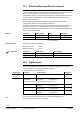
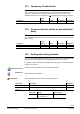
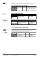
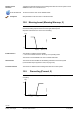
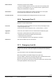
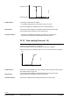
Table Of Contents
- RXB (KNX) applications library
- CLC and RAD description of functions for CC-02
- Table of contents
- 1 Introduction
- 2 Definitions / Tools
- 3 Select communications mode
- 4 Applications / Parameters
- 5 Room operating modes
- 5.1 Description
- 5.2 Overview
- 5.3 Determine the room operating mode with DESIGO (S-mode)
- 5.3.1 Local control of room operating mode via a window contact
- 5.3.2 Central control of room operating mode via input from the Use schedule
- 5.3.3 Central and local control of room operating modebased on occupancy
- 5.3.4 Central control of room operating mode via room operating mode schedule
- 5.3.5 Local control of room operating mode with a room unit
- 5.3.6 Local control of room operating mode via the Temporary Comfort mode input
- 5.3.7 Effective room operating mode
- 5.3.8 DESIGO examples
- 5.4 Determine the room operating mode with third-party products (S-mode)
- 5.4.1 Local control of room operating mode via window contact input
- 5.4.2 Central control of room operating mode with an input from the room operating mode schedule
- 5.4.3 Central control of the room operating mode via the schedules Use and Occupancy
- 5.4.4 Central and local control of room operating mode based on occupancy
- 5.4.5 Local control of room operating mode with a room unit
- 5.4.6 Local control of room operating mode via the Temporary Comfort mode input
- 5.4.7 Effective room operating mode
- 5.4.8 Third-party (S-mode) examples
- 5.5 Determine the room operating mode with Synco (LTE mode)
- 5.5.1 Local control of room operating mode via window contact input
- 5.5.2 Central room operating mode control via Enable Comfort
- 5.5.3 Central control of room operating mode via room operating mode input
- 5.5.4 Local control of room operating mode via presence detector
- 5.5.5 Local control of room operating mode with a room unit
- 5.5.6 LTE mode examples
- 5.6 Determine the room operating mode without a bus (stand-alone)
- 6 Setpoint calculation
- 7 Temperature measurement
- 8 Control sequences
- 9 Master/slave
- 10 General / central functions
- 10.1 Send heartbeat and Receive timeout
- 10.2 Digital inputs
- 10.3 Temporary Comfort mode
- 10.4 Presence detector switch-on and switch-off delay
- 10.5 Heating and cooling demand
- 10.6 Heating/cooling signal output
- 10.7 Special functions
- 10.8 Morning boost (Morning Warmup, 2)
- 10.9 Precooling (Precool, 5)
- 10.10 Test mode (Test, 7)
- 10.11 Emergency heat (8)
- 10.12 Free cooling (Freecool, 10)
- 10.13 Alarm
- 10.14 Reset setpoint shift
- 10.15 Free inputs/outputs
- 10.16 Software version
- 10.17 Device state
- 11 Room unit
- 12 KNX information
- 12.1 Reset and startup response
- 12.2 LED flashing pattern
- 12.3 Startup delay
- 12.4 Bus load
- 12.5 S-mode communication objects for RAD/CLC
- 12.6 LTE-mode communication objects
- 12.7 HandyTool parameters by number
- 12.8 HandyTool parameters, alphabetical
- 12.9 HandyTool enumerations
- 12.10 Data point type description
- 13 FAQ
- 14 Integration of RXB in DESIGO/Synco
- 14.1 Case 1: Integration in Synco
- 14.2 Case 2: Integration in DESIGO
- 14.3 Case 3: Display in DESIGO, with shared Synco schedule
- 14.4 Case 4: Display in DESIGO/Synco, with shared Synco schedule
- 14.5 Case 5: Display in DESIGO, separate schedules
- 14.6 Case 6: Separate display, separate schedules
- 14.7 Case 7: Separate display, shared Synco schedule
- 15 Working with different tools

102/140
Siemens RXB (KNX) Applications library CLC and RAD description of functions for CC-02 CM110384en_04
Building Technologies General / central functions 21 Sep 2010
10.1 Send heartbeat and Receive timeout
In a KNX network, S-mode and LTE mode communication objects can be exchanged
between individual devices. The receive
timeout defines the period of time within which
all communication objects of a device must be received at least once. If a
communication object is not received within this period, a predefined value is used and
an error message generated. This ensures that interruptions in communication are
identified at an early stage.
Similarly, send
heartbeat defines the period of time within which all requested
communication objects must be transmitted at least once.
The time intervals are based on the size of the network. Normally the basic setting can
be retained. In the case of S-mode communication objects, shorter times may be
selected for smaller networks or for test purposes. The receive timeout must always be
longer than the send heartbeat.
Parameter Basic setting Range Resolution
Receive timeout 60 min 0 ... 105 min 5 min
Send heartbeat 45 min 0 ... 105 min 5 min
(0 = not enabled)
Fixed times are specified as follows:
Receive timeout: 31 min
Send heartbeat: 15 min
HandyTool
Parameter Short name Basic setting
*128 Receive timeout 60 min
*127 Send heartbeat 45 min
10.2 Digital inputs
The following potential-free contacts can be connected to digital inputs D1 and D2:
Presence detector or window contact (see section 5).
Dewpoint sensor (see section 8.2.5).
Digital input Function Contact action HandyTool
Input 1
Input 2
*113
*114
Not used by the
application
Free: Bus = 1 = Contact closed
Free: Bus = 1 = Contact open
0 = Default
1
(Free input, contact can be used freely (see page 111).
Occupancy Occupied = Contact closed
Occupied = Contact open
2
3
Window Window open = Contact open
Window open = Contact closed
4
5
Dewpoint Dewpoint = Contact closed
Dewpoint = Contact open
8
9
Do not connect the same type of sensor / functions to both digital inputs.
The controller would ignore the second input.
S-Mode
LTE and S-mode
Note