RXB (KNX) applications library CLC and RAD description of functions for CC-02 (CLC and RAD applications: see document CM110671). Related documents CM1Y9775 CM1Y9776 CM1Y9777 CM1Y9779 CM110384en_04 21 Sep 2010 RXB integration, S-mode. RXB / RXL integration – Individual addressing. Third-party integration. Working with ETS.
Table of contents 1 1.1 1.2 1.3 1.4 1.5 1.6 1.7 1.7.1 1.7.2 Introduction .................................................................................................5 Revision history .............................................................................................5 Copyright .......................................................................................................5 Quality assurance .........................................................................................
5.4.8 5.5 5.5.1 5.5.2 5.5.3 5.5.4 5.5.5 5.5.6 5.6 5.6.1 5.6.2 5.6.3 5.6.4 Third-party (S-mode) examples .................................................................. 53 Determine the room operating mode with Synco (LTE mode).................... 55 Local control of room operating mode via window contact input ................ 56 Central room operating mode control via Enable Comfort.......................... 56 Central control of room operating mode via room operating mode input...
10 10.1 10.2 10.3 10.4 10.5 10.6 10.7 10.8 10.9 10.10 10.11 10.12 10.13 10.13.1 10.13.2 10.14 10.15 10.15.1 10.15.2 10.15.3 10.16 10.17 General / central functions .....................................................................100 Send heartbeat and Receive timeout ........................................................102 Digital inputs..............................................................................................102 Temporary Comfort mode ............................................
1 Introduction 1.1 Revision history CM110384en_03 21.09.2010 10.2 interchanged HandyTool settings 2 and 3 Removed "fan coil" CM110384en_03 28.02.2009 7.1.3 Temperature averaging 8.1.5 Downdraft compensation CM110384en_02 14.03.2008 CM110384en_01 30.11.2007 First edition 5.3.3, 5.4.4 Presence detector 8.1.1 Offset for motorized actuators (3rd party) 11.13.2 Alarm LTE: Alarm codes 12.9 Table "HandyTool enumerations" 1.
1.4 Document use / request to the reader Before using our products, it is important that you read the documents supplied with or ordered at the same time as the products (equipment, applications, tools etc.) carefully and in full. More information on the products and applications (e.g. system descriptions etc.) is available on the Internet/intranet at https://intranet10.sbt.siemens.com/business/building_comfort/systems/desigo/ra/.
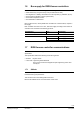
1.6 Bus supply for RXB Konnex controllers RXB controllers work without bus supply if the following conditions are adhered to: Parameterize only using the Handy Tool (not with ETS3 or ACS). No integration in a building automation and control system (e.g. DESIGO, Synco). No changeover operation (sensor signal via bus). No outdoor temperature via bus. No master/slave combinations. Else, the Konnex bus, used by RXB room controllers for communications, requires a bus supply.
1.7.2 LTE mode LTE mode was specifically designed to simplify engineering. Unlike with S-mode, there is no need to create the individual connections (group addresses) in the tool. The devices establish the connections themselves. Definitions To make this possible, the following was defined: Every device or sub-device is located within a zone. Every data point (input or output) is assigned to a zone. Every data point (input or output) has a precisely defined name.
2 Definitions / Tools 2.1 Signals and parameters (presentation) Inputs, outputs and parameters of an application can be influenced in various ways. This description of functions applies the following symbols: Room unit ETS3 Professional STOP The room unit influences parameters shown with this symbol. Parameters identified in this way are parameterized using ETS3 Professional (EIB tool software). Important! The RXB Konnex controllers CANNOT be parameterized with ETS2.
LTE-mode communication objects All communication objects operating in LTE mode are described as follows: HVACMode 1) TimeswitchZone 2) Possible partner function blocks 3) 110 HVACS HVAC-Mode Scheduler Known partner devices 4) Siemens: Synco RM700 104 PMC Program to HVAC-Mode Conversion Key 1) The name of the LTE communication object is entered here. 2) Each LTE communication object is assigned to a zone. This is recorded here. 3) This is where suitable partner function blocks are listed.
2.2 Supported tools The RXB Konnex controllers can be commissioned either with the Konnex tool ETS3 Professional, the Synco ACS Service too or the HandyTool. STOP Important! Be careful when using different tools. The following rule applies: Last one's right! When you use an OCI700 as the interface, connect it to the controller's or room unit's service socket. The OCI700 must be powered via USB by the computer as long as it is connected to the service socket.
2.4 ACS Service Parameterization using ACS This manual does not describe how physical addresses are defined. This information can be found in the ACS description. In the ACS Service program, select Plant, Open to open the plant.
2.5 HandyTool Parameterization using the HandyTool The HandyTool function is included in the QAX34.3 room unit allowing you to parameterize RXB room controllers (as of version 2.36). The following settings are possible in the room controllers: Parameters. Physical address. Zones. Group addresses (bindings) cannot be assigned. This must be carried out in ETS. QAX34.3 room unit In addition to its room unit functionality, this device also allows for parameterizing room controllers.
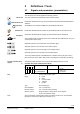
2.5.1 Operating HandyTool functions Function of the buttons + = Count / move up. – = Count / move down. (leave unconfirmed). < = Enter (confirm). 10385Z70 > = Escape Parameter position. Value to be adjusted. Display New start following important parameter changes e.g. P006 e.g. 22.5 (a temperature). or 250 (e.g. a particular type of actuator). The controller is restarted if certain configuration parameters are changed (e.g. *063 Actuator type). 2.5.
Adjustable parameters (parameterization mode) P001 P002 P003 P008 P009 P010 P011 P012 P013 P016 P017 P018 Physical address. Physical address. Physical address. Geographical zone (apartment). Geographical zone (room). Geographical zone (subzone). Time-switch zone (apartment). Time-switch zone (room). Time-switch zone (subzone). Heat distr zone heating surface. Refrig distr zone cooling surface. Outside temperature zone. P021 Master/Slave. P023 Master/Slave zone (group).
2.5.3 STOP Caution Major parameterization using room unit QAX34.3 This parameterization mode allows for changing also critical values. As a worst case scenario, components (controllers/actuators or other plant parts) may be destroyed. Start parameterization mode: Press buttons < , > and – simultaneously for about 2 s until the display turns dark. Release the buttons. Press button – twice briefly. Press buttons + and – simultaneously for approx. 2s The display goes dark.
2.6 Upload/download parameters using room unit QAX34.3 This function requires a QAX34.3 with index D or higher! The HandyTool can save 5 different controller parameter sets. These are uploaded from a fully parameterized controller using the Upload function. Download allows for transferring such a data set to one or several controllers (prerequisite: same controller type). The address, and for LTE the zones, must be adjusted (see 2.5.2). STOP Caution Download allows for changing also critical values.
2.7 Test the periphery using room unit QAX34.3 This function requires a QAX34.3 with index D or higher! The HandyTool allows you to test the connected field devices (sensors, actuators). This works only for the controller connected to the HandyTool; master/slave operation is not possible. An application must be selected and fully parameterized in the controller (address and zones can contain default values).
2) 4) 6) 7) 9) Monitor and operate T21 and T22 have the same effect in changeover applications. Only for RXB24.1/CC-02. If not used by the application. Operates only the I/Os of the controller in test mode, no bus actuators. Values are correct when read, but will not automatically be updated. The positions can be selected with < (Enter). The inputs are displayed Outputs can be set via < (Enter) and + / –. Exit test mode To exit test mode, press >- (Escape) 2 - 3 times (depending on the situation).
3 Select communications mode Section 1 shows that RXB room controllers can work in both S- and LTE mode. They are used in S-mode when networked with the DESIGO automation and control system, and in LTE mode with Synco. Note ETS3 Professional The factory setting of all controllers and the basic setting of the tools is 0 = S-Mode. This minimizes the bus load. Exception: ACS Service changes the setting immediately to 1 = LTE + S. The ETS3 Professional is used in DESIGO networks.
ACS Service The ACS service tool is used in Synco networks. It has access to LTE mode only. HandyTool *006 Communication mode 3.1 Setting 0 1 Mode S-mode LTE and S-mode Address zones in LTE mode (together with Synco) This section applies only to LTE mode. Zone addresses must be allocated in cases where RXB Konnex controllers are used in LTE mode (e.g. together with Synco). These must be defined together with the Synco devices at the planning stage.
Outside temperature zone Zone The outside temperature is exchanged in this zone (all Synco 700 devices). = ---, 1...31 Master/slave zone (Apartment . Room . Subzone) Apartment = ---, 1...126 Room = ---, 0...63 Subzone = ---, 0...15 In cases where RXB controllers are to be operated in master/slave mode, a master/slave zone must also be defined. For the master, it is usual to enter the geographical zone of the master. The same master/slave zone is used for the slave as for the master.
ACS Professional Reduce bus load HandyTool The zones are defined under Communication. Individual zones can also be disabled via command if they are not being used. This has the advantage of reducing the load on the bus. See the parameter in the last column of the following table.
3.2 RXB application example with RMB795 for geographical and time switch zones The room group philosophy is applied to the following example. This example uses FNC applications. CLC and RAD applications, however, apply the same principle. Building floor plan The building has three stories used by different companies for their headquarters. The following companies rent offices on the third floor: – Company Sport AG with conference room and two offices.
Two room groups for Sport AG Let us know look at the floor plan for company Sport AG. The company required separation of the rooms into two room groups or two geographical zones (apartm) as follows: – Conference room (room group 1). – All other offices (room group 2). The RXB room controllers were entered in the floor plan, and the addresses assigned accordingly: x x x x x x x x SA EA Conference Enable Setpoint prio Relay 1 2 Room group 1 Q Q Conference room D: 114 G: 1.1.
The room and subzone are fixed (room = 1, subzone = 1). To set the room group at the control unit, the following applies: Room group = Geographical zone (apartment . 1 . 1). Room controller settings The following settings are available in the RXB room controllers: – Geographical zone (apartment). – Geographical zone (room). – Geographical zone (subzone). For HVAC applications with RXB room controllers, use only the geographical zone (apartment) and the geographical zone (room).
3.3 Implement application example The SyncoTM planning and commissioning protocol C3127 enables you to clearly draw plant and necessary communication settings. Proceed as follows: Procedure for planning 1. 2. 3. Enter general information such as plan name, device name, device types, applications, etc.. Copy the device addresses for the bus members along with the basic settings for communication from the building floor plan. Enter the geographical zone addresses as per the defined groups.
3.4 Heating and refrigeration demand zones The above described building is equipped with Synco controllers on the generation side. Konnex TP1 RMH760 Controller 1 RMB795 Controller 3 Controller 2 RXB... Controller 4 RXB... Controller 5 RXB...
4 Applications / Parameters 4.1 Select application Most of the RXB Konnex controllers store multiple applications (e.g. RXB24.1/CC-02 with CLC01, CLC02 and RAD01). The tool allows you to select the required application. Here, ETS3 Professional and ACS differ greatly. ETS3 Professional The tool displays all applications as devices. Adding a device defines the desired application. Select Engineering, Edit, Add Device, then select one or several devices in the product finder and enter them in the line.
HandyTool *005 Plant type Setting 1 2 3 4.2 Application CLC01 (CC-02) CLC02 (CC-02) RAD01 (CC-02) Parameter settings The following sections describe how to set parameters, with only slight differences between the two PC tools. The display is the main difference.
5 Room operating modes 5.1 Description The operating modes in DESIGO RXB are Comfort, Precomfort, Economy and Protection. In addition, the controller has a frost Protection limit, at which an alarm can be triggered. Each room operating mode has separately adjustable heating and cooling sequence setpoints. Heating Cooling Y [%] 10385D01 100 0 TR Comfort Precomfort Economy Protection Frost risk Y TR Output signal (valve or damper actuator). Room temperature.
RXB (KNX) Applications library Room operating modes Occupancy Building use Central S S PPS2 Controller S Temporary comfort mode Room unit DI S Presence detector DI S Window contact Local DESIGO Section 5.3 3. 3. 3. 2. 1. Prio Effective occupancy S Effective Room operating mode S S Room operating mode Central DI S Window contact Local PPS2 S Temporary comfort mode Room unit DI S Presence detector 3. 3. 3. 3. 1. 1.
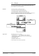
5.3 Determine the room operating mode with DESIGO (S-mode) In S-mode, the Effective room operating mode of the room controller depends on the central schedules for Use and Occupancy and/or on local influences such as window contacts, presence detectors, or room units. The illustration below shows how these influences are processed by the room controller along with their priority: Central Local Controller Window contact S DI Prio 1. S Effective room op. mode Building use S 2. S 3.
5.3.1 Central Local control of room operating mode via a window contact Local If a window is opened, the room controller always switches to room operating mode Protection, i.e. the heating or cooling output is reduced to a minimum. If a window is opened outside the building-in-use period, it is possible to, e.g., trigger an additional alarm in the building automation and control system. Controller Prio S DI 1. S 2. S 3. S S S DI 3. PPS2 S Effective room operating mode 3.
K N X CO R The state of the room controller (result of the logic OR operation) is mapped to the building automation and control system via the following S-mode communication object: Window contact output (Output communication object) Type Flags R W C T U Send heartbeat States 1 Yes 0 = Closed 1 = Open 0 1 1 0 1.019 DPT_WindowDoor Master/slave applications: Bindings are required in S-mode to communicate to the master the window contact state at the slave. Note 5.3.
K N X CO R The following S-mode communication object is used for schedule usage from a building automation and control system: Time schedule Use (input communication object) Type Flags R W C T U Receive timeout States 0 Yes 0 = In use 1 = Not in use 2 = Protection 1 1 0 5.3.3 Central 0 20.002 DPT_BuildingMode Central and local control of room operating mode based on occupancy Local Controller Prio S DI 1. S 2. S 3.
The presence detector has two states: State Description Occupied Unoccupied Effective occupancy Room is occupied. Room controller switches to Comfort. Room is not occupied. Room controller switches to Economy or Precomfort. The table below shows Effective occupancy as a function of the occupancy time schedule and the presence detector. Rule: Occupied takes precedence over unoccupied. If either the schedule or the presence detector transmits occupied, the room is occupied.
Presence detector The presence detector is connected directly to a digital input on the room controller (see page 102); alternatively an EIB/KNX presence detector connected to the EIB/KNX bus may be used (see diagram below). The two entries are OR-linked; if one of them signals presence, presence applies. Since EIB/KNX presence detectors are available from a variety of manufacturers, the name of the S-mode output communication object varies accordingly. Presence detector on DI Room controller RXB...
Effective occupancy (output communication object) Type Flags R W C T U Send heartbeat States 1 Yes 0 1 5.3.4 1 0 20.003 DPT_OccMode 0 = Occupied 1 = Standby 2 = Unoccupied Central control of room operating mode via room operating mode schedule DESIGO does not support this type of schedule. If nevertheless used, the room controller may produce errors. 5.3.5 Local control of room operating mode with a room unit Room unit Central Local Controller S DI Prio 1. S 2. S 3.
The table below shows the effect of the /Auto button on the Effective room operating mode of the room controller. Existing Effective Room unit New Effective room Manual operation of room op. mode display /Auto button operating mode Auto Comfort Precomfort if Effective occupancy = occupied or standby. Economy if Effective occupancy = unoccupied. Comfort Comfort for Temporary Comfort period 1) Protection, unchanged.
The communication object Temporary Comfort mode has two possible states: State Description 1 = Trigger Effective room operating mode is Comfort. Has no influence on the Effective room operating mode. 0 = Not used Effective room operating mode The change in the Effective room operating mode with Temporary Comfort mode only during the building-in-use period (Use schedule). The change in the Effective room operating mode is event-driven at the moment when the communication object is received.
The resultant Effective room operating mode is also available as 4 digital communication objects: Effective room operating mode Comfort (output communication object) Effective room operating mode Precomfort (output communication object) Effective room operating mode Economy (output communication object) Effective room operating mode Protection (output communication object) Type Flags R W C T U Send heartbeat States 1 Yes 0 = Off 1 = On 0 1 1 0 1.001 DPT_Switch 5.3.
Schedule Use Building in use 06:00 10385D02 22:00 Building not in use Building Protection Schedule occupancy Room 1 ... 3 Occupied. 08:00 12:00 13:00 17:00 Standby Window contact Room 3 Unoccupied.
Schedule Use Building in use 06:00 22:00 10385D03 Building not in use Building Protection Schedule occupancy Room 1 and 2 Occupied Standby 08:00 18:00 Unoccupied / Auto button on room unit Room 1 Auto 1) 2) 3) 1) 2) 3) Effective room operating mode Room 1 Comfort Precomfort Economy Protection Presence detector Room 2 Occupied 4) Unoccupied Effective room operating mode Room 2 Comfort 4) Precomfort Economy Protection 44/140 Siemens Building Technologies RXB (KNX) Applications library
5.4 Determine the room operating mode with third-party products (S-mode) In S-mode, the Effective room operating mode of the room controller depends on the central Room operating mode schedule and/or on local influences such as window contact, presence detector, or room unit. The illustration below shows how these influences are processed by the room controller along with their priority: Central Local Controller Window contact S Protection mode DI Prio 1. S Effective room op. mode 1.
5.4.1 Central Local control of room operating mode via window contact input Local Controller Prio S DI 1. S If a window is opened, the room controller always switches to room operating mode Protection, i.e. the heating or cooling output is reduced to a minimum. 1. 3. S S S DI 3. PPS2 S Effective room operating mode 3. 3. The table below shows the Effective room operating mode as a function of the window contact input.
K N X CO R The state of the room controller (result of the logic OR operation) is mapped to the building automation and control system via the following S-mode output communication object: Window contact output (output communication object) Note Type Flags R W C T U Send heartbeat States 1 Yes 0 = Closed 1 = Open 0 1 1 0 1.019 DPT_WindowDoor Master/slave applications: Bindings are required in S-mode to communicate to the master the window contact state at the slave. 5.4.
5.4.3 Central control of the room operating mode via the schedules Use and Occupancy Third-party S-mode does not support these schedules. If nevertheless used, the room controller may produce errors. 5.4.4 Central and local control of room operating mode based on occupancy Presence detector Central Local Controller A presence detector detects the presence of people in a room. Prio S 1. DI S 1. It controls the room operating mode of a room controller while the building is in use.
Since EIB/KNX presence detectors are available from a variety of manufacturers, the name of the S-mode output communication object varies accordingly. Presence detector on DI Room controller RXB...
5.4.5 Local control of room operating mode with a room unit Room unit Central Local Controller Prio S DI 1. S 1. The /Auto button on the room unit can be used like a presence button. The room user can enable or disable HVAC control. 3. S S DI 3. S 3. PPS2 S 3. The room unit is connected to the PPS2 interface on the room controller. It displays the Effective room operating mode in a simplified form, and can also be used to change it.
5.4.6 KNX R CO Local control of room operating mode via the Temporary Comfort mode input Central Local Controller Prio S 1. DI S 1. The Temporary Comfort mode communication object has an effect similar to that of the /Auto button on the room unit. However, HVAC control can only be enabled, i.e. the room operating mode switches to Comfort only. 3. S S 3. DI S 3. PPS2 3. S Any KNX/EIB button (pulse switch) can be used for entry: RXB...
The table below shows the effect of the Temporary Comfort mode on the Effective room operating mode of the room controller. Existing Effective room op. mode Temporary Comfort mode New Effective room operating mode Comfort Precomfort Economy 0 = Not used 1 = Trigger 1 = Trigger Protection. 1 = Trigger No effect. Comfort. Comfort for Temporary Comfort period 1). Protection, unchanged. Key: 1 means: "changes to 1 ".
5.4.8 Third-party (S-mode) examples The following examples show two typical applications of schedules and local control of the room operating mode. Rooms without room unit or presence detector Example 1 The room operating mode in Rooms 1..3 of a building is determined by the room operating mode schedule. Window contacts are installed in all rooms. The following conditions are specified: Overall, the building is in use from 06.00 to 20.00.
The following conditions are specified: The building is in use from 06.00 to 20.00 (Protection from 20.00 to 06.00). Rooms 1 and 2 must be available from 08.00 to 18.00 (Precomfort). The occupant(s) of room 1 are working overtime. At 18.00, the room operating mode changes to Economy, even if the room unit is set to Auto (1). Comfort mode can now be reactivated with the Auto switch on the room unit (2). Comfort remains active for the set Temporary Comfort mode period (see page 103).
5.5 Determine the room operating mode with Synco (LTE mode) In LTE-mode, the Effective room operating mode of the room controller depends on the central room operating mode schedule and/or on local influences such as window contact, presence detector, or room unit. The illustration below shows how these influences are processed by the room controller along with their priority: Central (ACS) Central (Synco controller) Local Controller Window contact DI Prio 0. 1. 1.
5.5.1 Local control of room operating mode via window contact input Window contact Local Central (ACS) Controller Prio Central (Synco controller) If a window is opened, the room controller always switches to room operating mode Protection, i.e. the heating or cooling output is reduced to a minimum. 0. DI 1. 1. 2. 3. DI PPS2 Effective room operating mode 3. 3. The table below shows the Effective room operating mode as a function of the window contact input.
K N X CO R The following LTE-mode communication object is provided for central control: Enable Comfort (input) Possible partner function blocks) Known partner devices EnableComfort 110 HVACS HVAC-Mode Scheduler Siemens: Synco RMB795 Timeswitch zone 104 PMC Programs to HVAC-Mode Conversion Possible states are: State Description Enabled Priority 3 influences (room operating mode input, presence detector, room unit) are enabled. Priority 3 influences are disabled.
Possible states are: Room operating mode Comfort Precomfort Economy Protection Effective room operating mode of room controller Comfort Precomfort Economy Protection The room operating modes Comfort, Precomfort and Economy have priority 3 fro the room controller, i.e. they can be changed by a presence detector or room unit. The Protection room operating mode has priority 1, i.e. presence detector and room units are disabled. Priorities 5.5.
5.5.5 Room unit Local control of room operating mode with a room unit Local Central (ACS) Controller Prio Central (Synco controller) 0. DI The /Auto button on the room unit can be used like a presence button. The room user can enable or disable HVAC control. 1. 1. 2. 3. DI PPS2 3. 3. The room unit is connected to the PPS2 interface on the room controller. It displays the Effective room operating mode in a simplified form, and can also be used to change it.
5.5.6 LTE mode examples The following examples show two typical applications of the schedule program and local control of the room operating mode. Rooms without room unit or presence detector Example 1 The room operating mode in Rooms 1..3 of a building is determined by the room operating mode schedule. Window contacts are installed in all rooms. The following conditions are specified: Overall, the building is in use from 06.00 to 20.00.
The following conditions are specified: The building is in use from 06.00 to 20.00 (Protection from 20.00 to 06.00). Rooms 1 and 2 must be available from 08.00 to 18.00 (Precomfort). The occupant(s) of room 1 are working overtime. At 18.00, the room operating mode changes to Economy, even if the room unit is set to Auto (1). Comfort mode can now be reactivated with the Auto switch on the room unit (2). Comfort remains active for the set Temporary Comfort mode period (see page 103).
5.6 Determine the room operating mode without a bus (stand-alone) If no bus is connected, the Effective room operating mode of the room controller depends on the local influences such as window contact, presence detector or room unit. The illustration below shows how these influences are processed by the room controller along with their priority: Local Controller Window contact DI Prio 1. Presence detector DI 3. PPS2 3.
5.6.1 Window contact Local control of room operating mode via a window contact input Local Controller Prio DI 1. DI 3. PPS2 3. If a window is opened, the room controller always switches to room operating mode Protection, i.e. the heating or cooling output is reduced to a minimum. The window contact is connected directly to a digital input of the room controller (see page 102).
Effective room operating mode The change in the Effective room operating mode is event-driven at exactly the time when the Effective occupancy changes. The room unit (which is also priority 3) can cause the Effective room operating mode to change again last command wins. Presence detector New Effective room operating mode Comfort (default) Economy. No presence detector Unoccupied (people leave room). Occupied (people enter room). Comfort Key: Occupied means: "changes to occupied ". 5.6.
Existing Effective room op. mode Room unit display Manual operation of /Auto button New Effective room operating mode Comfort Auto Precomfort if Effective occupancy = Occupied. Economy if Effective occupancy = Unoccupied. Comfort. Comfort for Temporary Comfort period 1). Protection, unchanged. Precomfort Economy Auto Auto Protection Auto Key: Auto means: "changes to Auto ". 1) Comfort mode is active for the predefined Temporary Comfort period (see page 103).
10385D70 Window contact Window open Room 1 Window closed / Auto button on room unit Room 1 Auto 1) 1) 2) 2) 2) 2) Comfort Effective room operating mode Room 1 Precomfort Economy Protection 10385D71 Window contact Window open Room 2 Window closed Presence detector Room 2 1) 1) Occupied Unoccupied Auto / Auto button on room unit Room 2 3) 2) 2) Comfort Effective room operating mode Room 2 Precomfort Economy Protection 10385D72 Window contact Window open Room 3 Window closed / Auto butto
6 Setpoint calculation 6.1 Description Each room controller knows 9 different room temperature setpoints: One heating and cooling setpoint each for the room operating modes Comfort, Precomfort, Economy, and Protection as well as Frost risk limit value. The setpoints are: – Defined in the tool during engineering. – Adjusted during runtime by the communication objects (DESIGO, Synco). This does not apply to Protection setpoints and Risk of frost limit values (page 31).
6.1.
6.2 Setpoint settings with the tool A tool is used to set the temperature setpoints for the room operating modes in each room controller. ETS3 Professional ACS Service Select the Room Temperature Setpoints tab.
HandyTool See the parameters in the last column of the following table. Name Protection cooling setpoint Economy cooling setpoint Precomfort cooling setpoint Comfort cooling setpoint Comfort heating setpoint Precomfort heating setpoint Economy heating setpoint Protection heating setpoint Setpoints Basic setting 40 °C 35 °C 28 °C 24 °C 21 °C 19 °C 15 °C 12 °C Range 1) 10 ... 40 °C 10 ... 40 °C 10 ... 40 °C 10 ... 40 °C 10 ... 40 °C 10 ... 40 °C 10 ... 40 °C 10 ... 40 °C Resolution 0.5 K 0.5 K 0.5 K 0.
In LTE-mode, the central setpoint setting is transmitted via the following communication objects (triplets): Setpoints heating (input) Setpoints cooling (input) TempRoomSetpSetHeat TempRoomSetpSetCool Possible partner function blocks) Known partner devices Siemens SBT proprietary Siemens: Synco RMB795 Geographical zone STOP Important! Setpoints changed by a tool (e.g. HandyTool) are overwritten by PX-KNX during room controller startup! 6.
K N X CO R In a building automation and control system, the central setpoint shift can be controlled via the following S-mode communication objects (triplets): Setpoint shift heating (input communication object) Setpoint shift cooling (input communication object) Type Flags R W C T U 0 1 1 0 0 222.
Function Comfort: – The Comfort setpoints for heating and cooling are shifted in parallel A . – The original spacing heating – cooling is maintained. Internal correction by controller The room controller corrects the setpoints as follows following a local shift: Precomfort:: – The values are shifted in parallel to the Comfort values B . – The cooling setpoint cannot be lowered following central shift C . – The heating setpoint cannot be increased following central shift C .
7 Temperature measurement 7.1 Room temperature measurement Sources The value valid for temperature control can originate in various sources: – A room unit via PPS2 7.1.1 – An analog sensor via analog input B1 7.1.2 7.1.3 – Mean value of several sensors – The bus. 7.1.
ETS3 Professional ACS Service Select tab General functions, Temperature sensor B1 (see page 100). Select General functions, Temperature sensor r B1 (see page 100). HandyTool See the parameters in the last column of the following table. Short name Temperature sensor B1 Room Only meas val acquisition No sensor Basic setting No sensor Parameter *092 1 3 255 Only meas val acquisition: Use of the signal: see "analog input B1", page 112. 7.1.
7.1.5 Temperature sensor outputs on the Konnex bus To map the local temperature measurement in a building automation and control system, the following two output communication objects are used: 10384Z15en RXB... Room controller Room temperature output O + Effective room temperature R The value of the communication object Room temperature output is not filtered (not smoothed). Sending takes place only if room "Room" is parameterized for the temperature sensor B1.
7.1.6 Temperature sensor input from Konnex bus The signal from the sensor connected to the bus takes priority. The signal is not averaged and no sensor correction (page 115) is done. Since KNX temperature sensors are available from a variety of manufacturers, the name of the S-mode output communication object varies accordingly. KNX Temperature sensor Room temperature input RaumTemperatur KNX R CO 10384Z16en RXB...
7.2 K N X CO R Outside air temperature via Konnex bus (CLC02, RAD01) The outside air temperature must be provided as bus information to all applications with radiators. It can be read via the following S-mode communication object: Outside temperature (input communication object) Type Flags R W C T U Receive timeout Value 0 Yes Floating point (°C) 1 1 1 1 9.
8 Control sequences 8.1 Radiator (RAD01) The radiator application has a continuous heating sequence. The room controllers operate with a PI algorithm optimized for thermal or motorized valve actuators. (For simplicity, the diagram below only shows the P-control action.) This application can also be used for other heating types, e.g. floor heating. However, the control parameters are not optimized for this.
Motorized KNX/EIB bus actuators The RXB2… room controllers also support the use of motorized EIB/KNX bus actuators. In the tool, select Motoric bus. Thermal valve actuators If thermal actuators are selected, Y1 / Y2 are always controlled in parallel to ensure that several actuators can be connected at the same time. It is not possible to ensure exact parallel running of more than one thermal valve actuator.
ACS Service HandyTool Select the actuator type from the Sequences menu: Parameter Short name Basic setting *063 Actuat h surf valve STA72E Settings STE71 STA71 1 3 SSA81 SSB81 10 11 STP71 4 SQS81 12 STA72E 5 SSP81 14 STP72E 6 Motoric bus El’mech 3rd party devices Thermal 3rd party devices Motoric 3rd party devices 250 252 253 254 With motorized actuators (conventional and bus actuators), third-party devices can also be connected.
ETS3 Professional ACS Service Select Sequences. After selecting third-party devices, a new window opens in which the heating runtime can be set. Select the actuator runtime from the Sequences menu: HandyTool See the parameters in the last column of the following table. Parameter Running time heat surf valve Offset heating surface valve Basic setting 150 s 0s Range 0 ... 360 s 0 ...
8.1.2 Values representing radiator valve actuator positions The position of the radiator valve is mapped to the bus. STOP Important! K N X CO R The Heating surface output communication object must NOT be used for applications for thermal valve actuators to control KNX/EIB valve actuators. With these applications, the communications objects have theoretical valve positions only.
ACS Service Select Sequences. HandyTool See the parameters in the last column of the following table. Short name Heat surf bus valve Range 0 = Disabled / Off, 1 = Enabled / On 8.1.3 Basic setting Disabled (0) HandyTool *086 Valve exercising feature To prevent valves from seizing after long periods of inactivity (e.g. cooling valve in winter), the valves are operated from time to time. The valve actuators are operated in such a way as to waste as little heating or cooling energy as possible.
8.1.5 Downdraft compensation This function is only active in Comfort mode. In situations where (owing to large internal heat gains) there is no heating demand from the room despite a low outdoor temperature (supplied via bus), large window surfaces can impair indoor comfort (through radiated cold, downward flow of cold air, condensation). Function A radiator located under the window can be used to slow the downward flow of cold air and compensate for cold radiation.
ETS3 Professional Select Sequences, Other setpoints: ACS Service Select Sequences, Other setpoints: HandyTool See the parameters in the last column of the following table. Parameter for downdraft compensation Outside temp 0% valve pos Outside temp max valve pos Maximum valve pos Enable the function Basic setting 0 °C –10 °C 100% Range –30 … 10 °C –30 … 10 °C 0 ... 100% Resolution 0.5 K 0.
8.2 Chilled ceiling (CLC01) The chilled ceiling application has a continuous cooling sequence. The room controllers operate with a PI algorithm optimized for thermal or motorized valve actuators. (For simplicity, the diagram below only shows the P-control action.) The control sequence comes into operation at the effective setpoints for cooling (see page 67). Y [%] C 100 YC 0 SpC 8.2.
Motorized and electromechanic valves HandyTool Parameter Running time cool surf valve Offset cooling surface valve 8.2.2 Basic setting 150 s 0s Range 0 ... 360 s 0 ... 360 s Resolution 1s 1s HandyTool *052 *054 Values representing chilled ceiling valve actuator positions The position of the chilled ceiling valve is mapped to the bus.
ETS3 Professional Select Sequences. The two fields at the bottom only are shown if "LTE and S-mode" are selected in the Communication menu.
8.2.3 Valve exercising feature To prevent valves from seizing after long periods of inactivity (e.g. cooling valve in winter), the valves are operated from time to time. The valve actuators are operated in such a way as to waste as little heating or cooling energy as possible. The valve exercising function is triggered if the valve has been closed for ca. 91 hours without interruption. 8.2.
8.2.6 Central/passive dewpoint monitoring The dewpoint can be monitored in two ways: – A dewpoint sensor with a potential-free contact is connected directly to a digital input of the room controller (see page 102). – Dewpoint sensor via bus. The two inputs are OR-linked: If one is active, dewpoint alarm applies. EIB / KNX Dewpoint sensor RXB...
8.3 Chilled ceiling and radiator 4-pipe (CLC02) The applications for chilled ceiling and radiator (4-pipe) each have a continuous heating and cooling sequence. The room controllers operate with a PI algorithm optimized for thermal or motorized valve actuators. (For simplicity, the diagram below only shows the P-control action.) The control sequences come into operation at the effective setpoints for heating and cooling (see page 67). Y [%] 100 80257 H C YH YC SpH SpC 0 8.3.
8.3.2 K N X CO R Override the valve actuator For test purposes, the following communication objects can be used to override chilled ceiling and radiator valve actuators. Heating surface valve override (input communication object) Type Flags R W C T U 0 1 1 0 0 8.010 DPT_Percent_V16 Receive timeout Value No 0...100% 0= 0% +100 = +100% +32767 = invalid Cooling surface valve override (input communication object) Note Type Flags R W C T U Receive timeout Value 0 No 0...100% 1 1 0 0 8.
9 Master/slave Example for master/slave: Several controllers are installed in a large, open-floor office. One controller (master) measures the room temperature and controls the other controllers (slaves) via the KNX bus. This ensures that future subdivision of the room into smaller rooms without the need to change the wiring is possible. EIB / KNX-Bus A B Master Slave Room 321 B Slave Room 322 Room 323 10385Z17 T Controller A is configured as the master and controls the room temperature.
9.
9.1.1 Window switch (S-Mode) For master/slave mode, only the master's window switch is evaluated without special measures, which also influences the slave controllers. If another window switch is also connected to the slave, it is NOT considered unless you create the following binding: Master Slave Window contact Input Window contact Output DI DI 10385Z118en This binding ensures that both controllers react when a window is opened.
9.2 LTE mode with zones The master/slave configuration is also possible in LTE mode. However, you are not required to create the individual connections but define the master/slave zone. Here too: The slave can be controlled only by one master, and master/slave bindings are possible only between same-version controllers (ASN) featuring the same applications and settings. ETS3 Professional Select Master/Slave: M Example Room Geogr. zone Master/slave M/S zone 321 5.1.1 Master 5.1.1 S 322 5.2.1 Slave 5.
The M/S function presupposes that all 3 M/S zones match. If the master/slave function is not required, the M/S zone should be disabled (to limit the load on the bus). Notes HandyTool Parameter Short name Basic setting *021 *022 *023 *024 Master/Slave M/S zone (apartm) M/S zone (room) M/S zone (subzone) Master 1 –1 (out of service) 1 Parameter *021 Master/Slave 9.2.
9.3 If more than one room unit is used in a master/slave configuration, only room units may be used with a button for setpoint shift. In the case of room units with a mechanical setpoint shift, only one room unit may be connected (combining room units with mechanical setpoint shift and room units with buttons for setpoint shift is not allowed). Room unit with button setpoint shift (several room units allowed). KNX / EIB Master RXB... RXB... Slave QAX34.1 QAX34.
10 ETS3 Professional General / central functions The following functions are enabled or configured via Edit parameters, Communication or General functions or Central functions. See Section 3 10.1 10.2 7.1.2 10.3 10.4 10.6 10.8 10.
ACS Service The following functions are enabled or configured under General functions or Central functions. 10.2 7.1.2 10.3 10.4 *) 10.14 *) Room number and Device name do not influence the application; they are used only for plant documentation purposes. We recommend to use this feature. HandyTool General and central functions are set using parameters 117 – 137 (see the individual sections for detailed information).
10.1 Send heartbeat and Receive timeout In a KNX network, S-mode and LTE mode communication objects can be exchanged between individual devices. The receive timeout defines the period of time within which all communication objects of a device must be received at least once. If a communication object is not received within this period, a predefined value is used and an error message generated. This ensures that interruptions in communication are identified at an early stage.
10.3 Temporary Comfort mode If the room controller is set to Economy and the associated room unit is switched to Auto (Comfort), the room controller maintains Comfort for the period defined by the temporary comfort mode time and then returns to Economy. This function is only available if the room unit concerned has an Auto button (see also pages 40 and 51). Basic setting 60 min Parameter Temporary Comfort mode 10.4 Range 0 ...
K N X CO R The heating or cooling demand can be evaluated via the S-mode communication object. Energy demand room (output communication object) Type Flags R W C T U Send heartbeat Value 1 Yes 0 1 1 0 6.001 DPT_Percent_V8 –100...100% : (-128 ...
10.7 K N X CO R Special functions The functions described in sections 10.8 and following are initiated via the following Smode communication object: Application mode (input communication object) Type Receive timeout Flags R W C T U 0 1 1 0 0 20.105 Yes DPT_HVACContrMode States 0 = Auto 1 = Heat 2 = Morning Warmup 3 = Cool 5 = Precool 6 = Off *) 7 = Test 8 = Emergency Heat 10 = Freecool Übrige Zustände nicht benutzt *) Exit from Test (7) is only possible with the sequence Off (6) + normal mode (0).
Disable special functions Triggering the special functions by the building automation and control system can be disabled in each room controller via tool. ETS3 Professional Go to the Functions menu for the disable feature. HandyTool See parameters in the last column of the above table. 10.8 Morning boost (Morning Warmup, 2) This function is used to raise the temperature in a room as quickly as possible to the Precomfort heating setpoint at the end of the night setback period.
Enable function The following condition must be fulfilled: The room controller must be in Economy or Precomfort room operating mode. The function can be disabled in the room controller via ETS3, together with free cooling; see central functions on page 100. Start function The function must be enabled via the building automation and control system (communication object Application mode, see page 105). Terminate function The function is disabled via the building automation and control system. 10.
10385D26 Emergency Heat Normal operation SpFr Enable function SpHPrt TR The following condition must be fulfilled: – The building temperature must be below the Risk of frost limit. The function CANNOT be disabled in the room controller with ETS3. Start function The function must be enabled via the building automation and control system (communication object Application mode, see page 105). Terminate function – The function is disabled via the building automation and control system.
10.13 Alarm Alarming works differently in S-mode and LTE mode. RXB controller support different alarms: PPS2 fault Room temp. sensor error Room air condensation If the connection to the room unit is faulty at the room controller (via PPS2 interface), the information is transmitted with this alarm message. Sensor interruption or short. No valid room temperature. Risk of condensation if temperature drops below dewpoint temperature. 10.13.
10.13.2 LTE mode Enable alarm info can also be operated in LTE mode. Here, two types of information are provided: AlarmInfo_CS and AlarmText_CS. With Synco, the user does not need to deal with this, as connection is opened automatically. The device in this case is active on the bus and sends its alarm as soon as it receives highest alarm priority. This ensures that the control station does not miss alarms.
10.15 Free inputs/outputs In a building automation and control system, the free I/Os can be used to e.g. query switching states or for direct switch control of another device over the network. However, these functions are not suitable for time-critical processes (<1 s). Free inputs can be defined as NC or NO (see 10.2). If not already in use, the following inputs and outputs can be used freely: RXB24.
10.15.2 KNX signals on digital/analog outputs RXB... Room controller 10384Z22en Y1 Triac Y1 Triac Y1 (input communication object) Triac Y2 (input communication object) Triac Y3 (input communication object) Triac Y4 (input communication object) Type Flags R W C T U 0 1 1 0 0 1.001 DPT_Switch Receive timeout States No 0 = Off (no voltage) 1 = On (AC 24V) 10.15.3 Mapping the sensor B1 to the Konnex bus RXB...
10.16 Software version The present software version can be read via the HandyTool. HandyTool Parameter Application set HandyTool *236 42A = RXB24.1/CC-02 42B = RXL24.1/CC-02 *237 *) *238 *) *239 *) Application version Operating system version KNX interface version *) This information serves to identify the controller's software version. You can use it in case of a service request. 10.17 Device state If the application is ready (loaded and tested), parameter 240 is set to 1.
11 Room unit ETS3 Professional Select Room unit: ACS Service Select Room unit: HandyTool See the parameters in the last column of the following table. Parameter Designation Measured value correction Setpoint offset range Local Comfort mode Room unit (fixed for HandyTool "With LCD") Temperature unit (only room units with LCD) Standard display (only room units with LCD) Setpoint display (only room units with LCD) Basic setting 0.
Sensor correction The measured value of the integrated temperature sensor can be corrected to compensate e.g. wall installation issues. Parameter Measured value correction Note Setpoint shift range Range – 3 ... 3 K Resolution 0,1 K HandyTool *101 This correction is also valid for a sensor that is connected to the analog input B1 (but not for a bus sensor). The maximum setpoint shift range is as follows (see also page 72).
Temperature display in normal mode In room units with an LCD, the temperature value to be displayed can be selected. (Normal mode = setpoint without shift or reset shift). Parameter Standard display LCD display (Only room units with LCD). HandyTool *109 No display Displays only the room operating mode and, if enabled, the heating or cooling symbol. 96 Setpoint Present temperature setpoint. 48 RAD01 = Heating setpoint. CLC01 = Cooling setpoint.
12 KNX information 12.1 Reset and startup response A reset is initiated under the following circumstances: Failure of the processor (e.g. watchdog). After a power failure. After a bus power failure. Upon completion of a self test (using communication object Status request). Via ETS (without startup delay) – After downloading the physical address – After downloading the parameters – Via ETS (menu Commissioning, Reset). After parameterization in ACS.
12.3 Startup delay After a reset, it takes up to 5 minutes for all connected room controllers to restart. This is designed to avoid overloading the mains power supply at startup. At the same time, it reduces the load on the KNX network, as not all controllers transmit data at the same time. The delay is determined by the device address of the controller. 12.
12.5 S-mode communication objects for RAD/CLC 12.5.
12.5.
Page LTE-mode communication objects Communication objects RXB controller TimeswitchZone A.R.S 57 Room operating mode 57 Enable Comfort 105 Application mode Communication objects Page 10385z21 12.6 Geographical zone A.R.
12.
RAD01 d S d S 115 Measured value correction d Setpoint offset range d Local Comfort mode 108 115 57 114 115 115 109 110 088 89 092 75 101 103 CLC02 S = Service(mode 6) ("Major parameterization") X 84 d = Display (display only) (mode 2) S Description d Parameter no. Heating surface output bus valve act.
HandyTool parameters, alphabetical CLC01 CLC02 S = Service(mode 6) ("Major parameterization") Name CC-02 P = Parameter (mode 3) ("Minor parameterization") d = Display (display only) (mode 2) Description Parameter no. Visible RAD01 12.
S = Service(mode 6) ("Major parameterization") RAD01 CLC01 CLC02 X X X S X X S X X S X X P S X X*) X d P S X X X d P S X X X Physical address (line address) d P S X X X X Parameter no. Description d = Display (display only) (mode 2) S 119 103 On-delay occupancy detector d Operating system version d 078 86 Outside temp 0% valve pos d 079 86 Outside temp max valve pos d 018 23 Outside temperature zone.
FNC HandyTool enumerations CLC / RAD 12.9 Physical address X X 5 Plant type X X FC-11 FC-12 6 Communications mode. X X 0 = S-Mode 1 = FNC02 1 = FNC10 1 = FNC03 1 = CLC01 Geographical zone X X 1 = S+LTE-M 2 = FNC04 2 = FNC12 2 = FNC05 2 = CLC02 X 3 = FNC08 3 = FNC18 X 4 = FNC20 No. 1-3 8 - 10 Parameter 11 -13 Time switch zone 14 X Heat distribution zone air heater. 15 Refrig distribution zone air cooler. 16 Heat distr zone heating surface FC-10 CC-02 3 = RAD01 .
12.10 Data point type description Instead of the previously referenced EIS data types, this document now references the new Konnex data point types. Where possible, the table which follows includes a reference to the corresponding EIS type. Data point types ID 1.001 Name DPT_Switch Format B(1) Unit Bit 1.003 DPT_Enable B(1) Bit 1.005 DPT_Alarm B(1) Bit 1.017 DPT_Trigger B(1) Bit 1.018 DPT_Occupancy B(1) Bit 1.019 DPT_Window_Door B(1) Bit 1.100 DPT_HeatCool B(1) Bit 5.
ID 219.001 Name DPT_AlarmInfo 222.100 DPT_TempRoom SetpSetF16[3] 222.101 DPT_TempRoom SetpSetShiftF16[3] Format U(8)U(8) N(8)N(8) B(8)B(8) F(16)F(16)F(16) Unit -- Range / coding Alarm description Corr.
13 FAQ Question: What happens if the parameter download process is interrupted? (power failure, bus failure etc.) Answer: The parameter set loaded into the controller is incomplete. The controller does not start properly. Valves may not open. Reload the parameters. Question: Why does the controller fail to start after a parameter download? (applies to HandyTool, ACS or ETS.) Parameter download was probably interrupted or exposed to interference.
Question: ACS: Parameter download does not work, why? Answer: Make sure that the parameter tree is expanded prior to download. Wrong Right Note Download sometimes also works with a collapsed parameter tree. Question: Why can I not parameterize the controller via HandyTool in service mode (n6)? Answer: There are two reasons: Download (HandyTool, ACS or ETS) was not exited correctly (interrupted). The controller was set to "unloaded" via ETS.
Question: Why does the slave window contact/occupancy contact have no effect? Answer for LTE mode: The slave window contact can only be integrated via the CFC. The corresponding compound is available on Swan Web: [WndStaDtr], [OcStaDtr]. Answer for S-mode: For one slave controller: Create group addresses for window contact and add communication object of master and slave. For one ore several slave controllers: In CFC by means of compound [WndStaDtr], [OcStaDtr].
14 Integration of RXB in DESIGO/Synco Combining RXB controllers with Synco and DESIGO integration is possible and sensible. However, certain types of combination are not allowed, and certain combinations are subject to specific conditions. Below are the most important combinations. Key Display Schedule 10385D69 Heat demand Refrigeration demand 14.1 – – Case 1: Integration in Synco Communication: Between the controllers:LTE mode via zones. With ACS: Individual addressing.
14.2 – – Case 2: Integration in DESIGO Communication: Between the controllers:S-mode. With DESIGO: Individual addressing or S-mode. RXB display: DESIGO RXB schedule: from DESIGO. Energy demand: to DESIGO. DESIGO INSIGHT ALN PXC... PXC...
14.3 – – STOP Important! Case 3: Display in DESIGO, with shared Synco schedule Communication: Between the controllers:LTE mode via zones. With DESIGO: Individual addressing or S-mode. RXB display: DESIGO Synco display: DESIGO RXB schedule: from Synco. Energy demand: to Synco. The DESIGO scheduler must be disabled by a specialist. Reason: Integration by means of individual addressing handles the schedule and display as one package. They subsequently need to be separated.
14.4 – – – STOP Important! Case 4: Display in DESIGO/Synco, with shared Synco schedule Communication: Between the controllers:LTE mode via zones. With DESIGO: Individual addressing or S-mode. With ACS: Individual addressing. RXB display: DESIGO and ACS. Synco display: DESIGO and ACS. RXB schedule: from Synco. Energy demand: to Synco. The DESIGO schedule must be disabled by a specialist. In theory, simultaneous display on DESIGO and Synco is possible.
14.5 – – STOP Important! Case 5: Display in DESIGO, separate schedules Communication: Between the controllers:LTE mode via zones. With DESIGO: Individual addressing or S-mode. RXB display: DESIGO Synco display: DESIGO RXB schedule: from DESIGO. Energy demand: to Synco. The RXB controllers use the DESIGO schedule. Synco controllers need a local Synco schedule. Both schedules must be synchronized. DESIGO INSIGHT ALN PXC... PXC...
14.6 – – – STOP Important! Case 6: Separate display, separate schedules Communication: Between the controllers:LTE mode via zones. With DESIGO: Individual addressing or S-mode. With ACS: Individual addressing. RXB display: DESIGO Synco display: ACS RXB schedule: from DESIGO. Energy demand: to Synco. The RXB controllers use the DESIGO schedule. Synco controllers need a local Synco schedule. Both schedules must be synchronized. DESIGO INSIGHT ALN ACS7.. PXC... PXC...
14.7 – – – STOP Important! Case 7: Separate display, shared Synco schedule Communication: Between the controllers:LTE mode via zones. With DESIGO: Individual addressing or S-mode. With ACS: Individual addressing. RXB display: DESIGO Synco display: ACS RXB schedule: from Synco. Energy demand: to Synco. The DESIGO schedule must be disabled by a specialist. DESIGO INSIGHT ALN ACS7.. PXC... PXC...
15 Working with different tools It is possible to prepare the RXB controllers in the office (parameterize in advance) so that only the physical address has to be entered on site. To this end, the HandyTool offers its “small parameterization”. In this case, preparatory work is probably carried out with ACS or ETS rather than the HandyTool. Special caution is required (data consistency) when using more than one tool.
/140 Siemens Building Technologies RXB (KNX) Applications library Working with different tools CLC and RAD description of functions for CC-02 CM110384en_04 21 Sep 2010