RXB application library (KNX) CLC & RAD – chilled ceiling and radiator applications from CC-02 (CLC and RAD functions description: see document CM110384). Table of contents LTHW radiator ................................................................................................................ 3 Chilled ceiling ................................................................................................................ 7 Chilled ceiling and radiator .................................................
/16 Siemens Building Technologies RXB application library (KNX) CLC & RAD – chilled ceiling and radiator applications from CC-02 CM110671en_02 14.03.
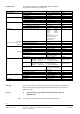
RAD01 LTHW radiator K NX • • • R Heating with LTHW radiator Continuous heating valve. Downdraft compensation Plant diagram B1 N1 R1 B1 D1 D2 YH Room controller. Room unit with temp. sensor. Outdoor temp sensor via KNX bus Window switch. Presence detector. Heating valve. T R1 D1 D2 10671S01 YH N1 KNX R Operating diagram Y [%] 100 Y TR SpH H YH Output signal. Room temperature. Effective heating setpoint Heating sequence. Heating valve.
Functions Function Continuous heating sequence Temperature measurement. Outside temperature (for downdraft compensation) Room operating modes. Setpoint shift. General functions. Room units. Compatible controllers. Application RAD01 includes the following functions (refer to the description of functions CM110384 for detailed information): Brief description – PI control. – Continuous heating control sequence.
YH.2 3) Connection diagram YH.3 D1 2) D2 2) YH.1 3) M Y2 G B2 Y1 M YH.1 KNX 3) R1 T 3 4 2 1 QAX... M B T RXB24.1 10671A01 D2 Y1 G Y2 19 19 21 21 N1 CE– GND CE+ D1 17 18 CE– N.C. CE+ M 10 11 12 13 14 15 16 CP+ 9 CP– 8 Y4 7 G 6 Y3 5 L 4 L 3 N 2 N 1 B1 B1 AC 230 V N L Connection variants for valve actuators Radiator Thermal Motorized Bus List of equipment Ref. N1 R1 B1 B2 D1 D2 YH.1 YH.2 YH.
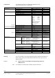
Configuration The following parameters are available with application RAD01. They are set via ETS, ACS, or HandyTool. Menu Parameters. Values/Range Basic setting Communication Communication mode Receive timeout Send heartbeat Comfort heating setpoint Precomfort heating setpoint Economy heating setpoint Protection heating setpoint Downdraft compensation S-mode / LTE and S-mode 0 ... 105 min. 0 ... 105 min. 10 ... 40 °C 10 ... 40 °C 10 ... 40 °C 10 ... 40 °C S-mode. 60 min. 45 min.
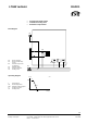
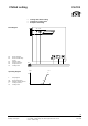
CLC01 Chilled ceiling K NX • • • Cooling with chilled ceiling. Continuous cooling valve. Dewpoint monitoring. D1 D2 D3 YC Room controller. Room unit with temp. sensor. Window switch. Presence detector. Dewpoint sensor Cooling valve. Operating diagram YC D3 T R1 D1 D2 10671S02 Plant diagram N1 R1 R N1 KNX R 70283 Y [%] C 100 Y TR SpC C YC Output signal. Room temperature. Effective cooling setpoint Cooling sequence. Cooling valve.
Functions Function Continuous cooling sequence Dewpoint sensor Temperature measurement. Room operating modes. Setpoint shift. General functions. Room units. Compatible controllers. Application CLC01 includes the following functions (refer to the description of functions CM110384 for detailed information): Brief description – PI control. – Continuous control sequence, cooling. – Control of thermal / electromechanic / motorized valve actuators (AC 24 V, PDM / AC 24 V, 2-position / AC 24 V, 3-position).
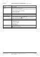
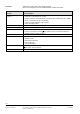
D3 2) Connection diagram YC.2 3) YC.3 B1 D1 2) D2 2) YC.1 G 3) M Y2 Y1 M YC.1 3) KNX R1 T 7 8 9 10 11 12 13 14 15 16 M N.C. D1 GND D2 Y1 G Y2 Y3 19 19 21 21 RXB24.1 10671A02 CE– CE+ CE– CE+ CP+ CP– Y4 G N1 17 18 L L 3 6 4 5 1 4 2 B M 3 N 2 N 1 B1 QAX... AC 230 V N L Connection variants for valve actuators Radiator (YH) – Chilled ceiling (YC) Thermal Motorized Bus List of equipment Ref. N1 R1 B1 D1 D2 D3 YC.1 YC.2 YC.
The following parameters are available with application CLC01. They are set via ETS, ACS, or HandyTool. Configuration Menu Parameters. Values/Range Basic setting Communication Communication mode Receive timeout Send heartbeat Protection cooling setpoint Economy cooling setpoint Precomfort cooling setpoint Comfort cooling setpoint Actuator type cool surf valve S-mode / LTE and S-mode 0 ... 105 min. 0 ... 105 min. 10 ... 40 °C 10 ... 40 °C 10 ... 40 °C 10 ... 40 °C S-mode. 60 min. 45 min.
CLC02 Chilled ceiling and radiator K NX • • • • R Heating with radiator and cooling with chilled ceiling. Modulating control of heating and cooling valve. Downdraft compensation Dewpoint monitoring. Plant diagram YC D3 B1 N1 R1 B1 D1 D2 D3 YH YC Room controller. Room unit with temp. sensor. Outside temp sensor via KNX bus Window switch. Presence detector. Dewpoint sensor Heating valve. Cooling valve.
Functions Function Continuous heating and cooling sequence. Dewpoint sensor. Temperature measurement. Outside temperature (for downdraft compensation). Room operating modes. Setpoint shift. General functions. Room units. Compatible controllers. Application CLC02 includes the following functions (refer to the description of functions CM110384 for detailed information): Brief description – PI control. – Two proportional control sequences, heating and cooling.
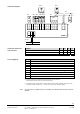
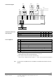
YH.2 3) YC.2 3) B2 D1 2) D2 2) YH.1 G Y1 G M Y2 Y1 M YH.3 . . . . . . . . . . . . . . . YC.3 M M Y2 D3 2) Connection diagram KNX YC.1 R1 T 3 4 2 1 QAX... M B T Y1 G Y2 RXB24.1 19 19 21 21 10671A03 D2 CE– GND N1 17 18 CE+ D1 CE– N.C. CE+ M 10 11 12 13 14 15 16 CP+ 9 CP– 8 Y4 7 G 6 Y3 5 L 4 L 3 N 2 N 1 B1 B1 AC 230 V N L List of equipment Ref. N1 R1 B1 B2 D1 D2 D3 YH.1 / YC.1 YH.2 / YC.
Configuration The following parameters are available with application CLC02. They are set via ETS, ACS, or HandyTool. Menu Parameters. Values/Range Basic setting Communication Communication mode Receive timeout Send heartbeat Protection cooling setpoint Economy cooling setpoint Precomfort cooling setpoint Comfort cooling setpoint Comfort heating setpoint Precomfort heating setpoint Economy heating setpoint Protection heating setpoint Downdraft compensation S-mode / LTE and S-mode 0 ... 105 min. 0 ..
Ordering The room controllers can be ordered preloaded with the application described here. When ordering, specify the quantity, DESIGO RXB device name, type code and application group. Example 15 Note Room controllers, type RXB24.1 with application group CC-02. RXB24.1/CC-02 The controllers are delivered with the basic settings shown above.
/16 Siemens Building Technologies RXB application library (KNX) CLC & RAD – chilled ceiling and radiator applications from CC-02 CLC02 – Chilled ceiling and radiator CM110671en_02 14.03.