
Operating Instructions

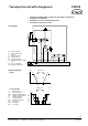
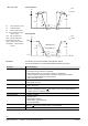
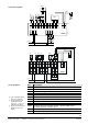
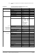
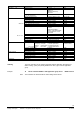

Table Of Contents
- RXB applications library (KNX)
- RXB – Fan coil applications from FC10, FC11, FC12, FC-13
- FNC02 - Two-pipe fan coil with changeover
- FNC03 - Two-pipe fan coil with changeover and electric reheater
- FNC04 - Four-pipe fan coil
- FNC05 - Four-pipe fan coil with electric reheater
- FNC08 - Four-pipe fan coil with room supply air cascade
- FNC10 - Two-pipe fan coil with changeover and outside air damper
- FNC12 - Four-pipe fan coil with outside air damper
- FNC18 - Two-pipe fan coil (changeover) and radiator
- FNC20 - Four-pipe fan coil, controlled by one damper

5/54
Siemens RXB application library (KNX) RXB – Fan coil applications from FC-10, FC-11, FC-12, FC-13 CM110672en_05
Building Technologies 1BFNC02 – Two-pipe fan coil with changeover 2013-06-07
Y1
G
Y2
YHC.2
3)
M
KNX
D3
T
4)
1
2
3
Q1
N
L
AC 230 V
1 2 4 5 6 7 8 9 10 11 12 13 14 15 16 17 18
M
D1
GND
D2
Y1
G
Y2
CP–
CP+
B1
25 26 27
RXB21.1
Q13
Q14
Y3
G
Y4
Q24
Q34
2819 21
N
L
N
21
L
CE–
CE+
19
N1
M
B
B1
T
D1
2)
D2
2)
2
1
4
3
QAX...
R1
10385A01
CE–
CE+
YHC.1
3)
N.C.
3
G0
G
Y
YHC.3
M
KNX
D5
T
RXB39.1
N1
D1
2)
D2
2)
2
1
4
3
QAX...
R1
10672A11
CP –
CP +
CE
–
CE +
1 2 3 4 5 6 7 8 9 10 11 12 13 14 15 16 17 18
M
D1
GND
D2
B1
23 24 25 26
Q13
Q14
Q33
19 19 21
N
L
N
21
L
CE
–
CE +
B2
29 30 31 32
D3
GND
D4
N.C.
YC1
G0
G
YC2
G0
YC3
27
Q34
N.C.
M
B
T
M
B
T
B1
N
L
AC 230 V
0
Y
Q2
D3
N
L
Ref.
Description
N1
Room controller.
R1
Room unit
B1
Return air temperature sensor, room temperature sensor.
D1
Window contact
2)
.
D2
Presence detector
2)
.
D3
Air flow monitor
D3 / D5
Changeover signal via KNX bus.
Q1
1- or 3-speed fan
4)
.
Q2
Continuous fan with DC 0...10 V control
YHC.1
Heating/cooling valve actuator, thermal, 2-position (PDM) control
3)
or electromechanic, 2-position control
YHC.2
Heating/cooling valve actuator, motorized, 3-position control
3)
.
YHC.3
Heating/cooling valve actuator DC 0...10 V
Connection diagrams
List of equipment
2) Type of operation (N/O or
N/C) can be selected.
3) Do not exceed the max.
simultaneous load on
outputs Y1 ... Y4: 9.5 VA
(see data sheet 3873).
4) Do not connect the fans in
parallel (or use cut-off
relays).