
Operating Instructions
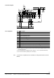
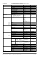

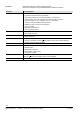
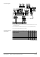
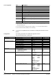
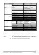

Table Of Contents
- RXB applications library (KNX)
- RXB – Fan coil applications from FC10, FC11, FC12, FC-13
- FNC02 - Two-pipe fan coil with changeover
- FNC03 - Two-pipe fan coil with changeover and electric reheater
- FNC04 - Four-pipe fan coil
- FNC05 - Four-pipe fan coil with electric reheater
- FNC08 - Four-pipe fan coil with room supply air cascade
- FNC10 - Two-pipe fan coil with changeover and outside air damper
- FNC12 - Four-pipe fan coil with outside air damper
- FNC18 - Two-pipe fan coil (changeover) and radiator
- FNC20 - Four-pipe fan coil, controlled by one damper

48/54
Siemens RXB application library (KNX) RXB – Fan coil applications from FC-10, FC-11, FC-12, FC-13 CM110672en_05
Building Technologies 8BFNC18 – Two-pipe fan coil (changeover) and radiator 2013-06-07
Ref.
Description
N1
Room temperature controller.
R1
Room unit
B1
Return air temperature sensor, room temperature sensor.
B2
Outside air temperature sensor via KNX bus.
D1
Window contact
2)
.
D2
Presence detector
2)
.
D3
Changeover signal via KNX bus.
Q1
1...3-speed fan
4)
.
YH.1, YHC.1
Radiator valve, heating/cooling valve, thermal, 2-position control
(PDM)
3)
.
YH.2, YHC.2 Radiator valve, heating/cooling valve, motorized, 3-position control
(PDM)
3)
.
YH.3, YHC.3
Radiator valve, heating/cooling valve, bus.
2) Type of operation and allocation to inputs D1 and D2 can be selected. Identical devices must not be
connected to both inputs.
3) Do not exceed the max. simultaneous load on outputs Y1...Y4: 9.5 VA (see data sheet 3873).
4) Do not connect the fans in parallel (or use cut-off relays).
A current list of compatible devices is available in the Desigo RX hardware overview
(N3804).
The following parameters are available with application FNC18.
They are set via ETS, ACS, or HandyTool.
Menu
Parameters.
Values/Range
Basic setting
Communication
Communication mode
S-mode / LTE and S-mode
S-mode.
Receive timeout
0...105 min.
60 min.
Send heartbeat
0...105 min.
45 min.
Room temperature setpoints
Protection cooling setpoint
10...40 °C
40 °C
Economy cooling setpoint 10...40 °C 35 °C
Precomfort cooling setpoint
10...40 °C
28 °C
Comfort cooling setpoint
10...40 °C
24 °C
Comfort heating setpoint
10...40 °C
21 °C
Precomfort heating setpoint 10...40 °C 19 °C
Economy heating setpoint
10...40 °C
15 °C
Protection heating setpoint
10...40 °C
12 °C
Other setpoints Downdraft compensation
Outside temp 0% valve pos
Outside temp max valve pos
Maximum valve pos
–30...10°C
–30...10°C
0...100%
0°C
–10°C
100%
Sequences Control sequence – Heating only
– Cooling only
– Changeover
Cooling only
Actuator type heating/cooling coil valve
– STA71 – SSA81
– STA72E – SSB81
– STE71 – SSP81
– STE72 – SQS81
– STP71
– STP72E
– Motorized 3rd devices
– Thermal 3
rd
devices
– Motorized bus
STP72E
Actuator type heating surface valve
– STA71 – SSA81
– STA72E – SSB81
– STE71 – SSP81
– STP71 – SQS81
– STP72E
– Motorized 3rd devices
– Thermal 3
rd
devices
– Motorized bus
STA72E
List of equipment
Note
Configuration