
Operating Instructions
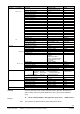

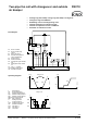
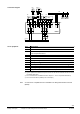
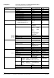

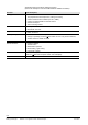
Table Of Contents
- RXB applications library (KNX)
- RXB – Fan coil applications from FC10, FC11, FC12, FC-13
- FNC02 - Two-pipe fan coil with changeover
- FNC03 - Two-pipe fan coil with changeover and electric reheater
- FNC04 - Four-pipe fan coil
- FNC05 - Four-pipe fan coil with electric reheater
- FNC08 - Four-pipe fan coil with room supply air cascade
- FNC10 - Two-pipe fan coil with changeover and outside air damper
- FNC12 - Four-pipe fan coil with outside air damper
- FNC18 - Two-pipe fan coil (changeover) and radiator
- FNC20 - Four-pipe fan coil, controlled by one damper

33/54
Siemens RXB application library (KNX) RXB – Fan coil applications from FC-10, FC-11, FC-12, FC-13 CM110672en_05
Building Technologies 6BFNC10 – Two-pipe fan coil with changeover and outside air damper 2013-06-07
Two-pipe fan coil with changeover and outside
air damper
FNC10
• Heating only (with LTHW), cooling only (with CHW) or changeover.
• Changeover signal via KNX bus.
• Modulating control of heating/cooling valve.
• Outside air damper for outside air supply.
• Outside air temperature sensor via KNX bus.
• Automatic or manual fan control.
Plant diagram
N1 Room controller.
R1 Room unit with temp.
sensor.
B1 Return air sensor.
B2 Outside air temperature
sensor via KNX bus.
D1 Window switch.
D2 Presence detector.
D3 Changeover signal via KNX
bus.
D4 Safety thermostat, outside
air.
Q1 Fan (1… 3-speed).
YHC Heating/cooling valve.
YM Outside air damper.
10385S19
M T
YM
B1
Q1
B2
N1
R1
D1 D2
T
YHC
D3
D4
KNX
R
Operating diagrams
100
0
TR [°C]
Y [%]
SpH SpC
Change-over
YHCYHC
H
C
10385D45
TO [°C]
Y [%]
SpC
100
0
SpEcm
SpFr
min
10385D44
YM
Y Output signal.
TR Room temperature.
TO Outside air temperature.
SpH Effective heating setpoint.
SpC Effective cooling setpoint.
SpEcm Economizer setpoint.
SpFr Risk of frost limit
H Heating sequence.
C Cooling sequence.
YHC Heating/cooling valve.
YM Outside air damper.
Q14 Fan speed 1.
Q24 Fan speed 2.
Q34 Fan speed 3.
10385D46
Change-over
TR [°C]
Y
H
C
Q14
Q24
Q34
SpH SpC