
Operating Instructions
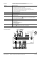
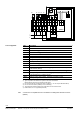
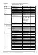
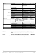
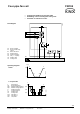
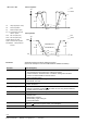
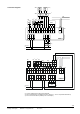
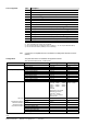
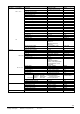
Table Of Contents
- RXB applications library (KNX)
- RXB – Fan coil applications from FC10, FC11, FC12, FC-13
- FNC02 - Two-pipe fan coil with changeover
- FNC03 - Two-pipe fan coil with changeover and electric reheater
- FNC04 - Four-pipe fan coil
- FNC05 - Four-pipe fan coil with electric reheater
- FNC08 - Four-pipe fan coil with room supply air cascade
- FNC10 - Two-pipe fan coil with changeover and outside air damper
- FNC12 - Four-pipe fan coil with outside air damper
- FNC18 - Two-pipe fan coil (changeover) and radiator
- FNC20 - Four-pipe fan coil, controlled by one damper

12/54
Siemens RXB application library (KNX) RXB – Fan coil applications from FC-10, FC-11, FC-12, FC-13 CM110672en_05
Building Technologies 2BFNC03 – Two-pipe fan coil with changeover and electric reheater 2013-06-07
G0
G
Y
YHC.3
M
KNX
D5
T
RXB39.1
N1
D1
2)
D2
2)
2
1
4
3
QAX...
R1
10672A12
CP –
CP +
CE
–
CE +
1 2 3 4 5 6 7 8 9 10 11 12 13 14 15 16 17 18
M
D1
GND
D2
B1
23 24 25 26
Q13
Q14
Q33
19 19 21
N
L
N
21
L
CE
–
CE +
B2
29 30 31 32
D3
GND
D4
N.C.
YC1
G0
G
YC2
G0
YC3
27
Q34
N.C.
M
B
T
M
B
T
B1
N
L
AC 230 V
0
Y
Q2
D3
N
L
Y
0
YR.1
N
L
F1
D4
T
YR
Ref.
Description
N1
Room controller.
R1
Room unit
B1
Return air temperature sensor, room temperature sensor.
D1
Window contact
2)
.
D2
Presence detector
2)
.
D3
Air flow monitor
D3 / D4
Safety thermostat, electric heating coil.
D4 / D5
Changeover signal via KNX bus.
Q1
1-...3-speed fan.
Q2
Continuous fan with DC 0...10 V control
YR
Electric reheater
6)
.
YR.1
Power controller (PWM or modulating), e.g. SEM61.4 + SEA45.1 (data
sheets N5102, N4937)
F1
External fuse, max. 10 A
7)
.
YHC.1
Heating/cooling valve actuator, thermal, 2-position (PDM) control
3)
or electromechanic, 2-position control
3)
YHC.2
Heating/cooling valve actuator, motorized, 3-position control
3)
.
YHC.3
Heating/cooling valve actuator DC 0...10 V
2) Type of operation and allocation to inputs D1 and D2 can be selected.
Identical devices must not be connected to both inputs.
3) Do not exceed the max. simultaneous load on outputs Y1...Y4: 9.5 VA (see data sheet 3873).
4) Do not connect the fans in parallel (or use cut-off relays).
6) The output of the electric heating coil at output Q44 must not exceed 1.8 kW.
7) External fuse, max. 10 A (protects pcb tracks).
A current list of compatible devices is available in the Desigo RX hardware overview
(N3804).
List of equipment
Note