
Operating Instructions
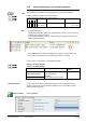
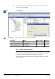
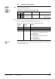
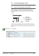
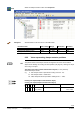
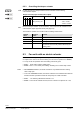
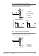
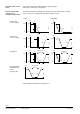
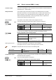
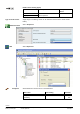
Table Of Contents
- RXB (KNX) applications library
- RXB Description of functions for FC10, FC11, FC12, FC13
- Table of contents
- 1 Introduction
- 2 Definitions / Tools
- 3 Select communication mode
- 4 Applications, parameters
- 5 Room operating modes
- 5.1 Description
- 5.2 Overview
- 5.3 Determine the room operating mode in Desigo (S-mode)
- 5.3.1 Local control of room operating mode via a window contact
- 5.3.2 Central control of room operating mode via input from the Use time schedule
- 5.3.3 Central and local control of room operating modebased on occupancy
- 5.3.4 Central control of room operating mode viathe Room operating mode time schedule
- 5.3.5 Local control of room operating mode with a room unit
- 5.3.6 Local control of room operating mode via the Temporary Comfort mode input
- 5.3.7 Effective room operating mode
- 5.3.8 Desigo examples
- 5.4 Determine the room operating mode with third-party products (S-mode)
- 5.4.1 Local control of room operating mode via the window contact input
- 5.4.2 Central control of room operating mode via the Room operating mode time schedule
- 5.4.3 Central control of room operating mode via the Use and Occupancy time schedules
- 5.4.4 Central and local control of room operating modebased on occupancy
- 5.4.5 Local control of room operating mode with a room unit
- 5.4.6 Local control of room operating mode via the Temporary Comfort mode input
- 5.4.7 Effective room operating mode
- 5.4.8 Third-party (S-mode) examples
- 5.5 Determine the room operating mode with Synco (LTE mode)
- 5.5.1 Local control of room operating mode via the window contact input
- 5.5.2 Central control of the room operating mode via Enable Comfort
- 5.5.3 Central control of room operating mode via Room operating mode input
- 5.5.4 Local control of room operating mode via presence detector
- 5.5.5 Local control of room operating mode with a room unit
- 5.5.6 LTE-Mode Examples
- 5.6 Determine the room operating mode without a bus (stand-alone)
- 6 Setpoint calculation
- 7 Temperature measurement
- 8 Control sequences
- 9 Fan control
- 10 Master/slave
- 11 General and central functions
- 11.1 Send heartbeat and receive timeouts
- 11.2 Digital inputs
- 11.3 Temporary Comfort mode
- 11.4 Presence detector switch-on and switchoff delay
- 11.5 Heating and cooling demand
- 11.6 Heating/cooling signal output
- 11.7 Special functions
- 11.8 Boost heating (Morning Warmup, 2)
- 11.9 Night purge (Night Purge, 4), (FNC10, FNC12)
- 11.10 Precooling (Precool, 5)
- 11.11 Test mode (Test, 7)
- 11.12 Emergency heating (Emergency Heat, 8)
- 11.13 Rapid ventilation (Fan only, 9)
- 11.14 Free cooling (Freecool, 10)
- 11.15 Alarm
- 11.16 Reset the setpoint shift
- 11.17 Free inputs/outputs
- 11.18 Software version
- 11.19 Device state
- 12 Room unit
- 13 KNX information
- 14 FAQs
- 15 Integrate RXB in Desigo/Synco
- 15.1 Case 1: Integration into Synco
- 15.2 Case 2: Integration into Desigo
- 15.3 Case 3: Display in Desigo, with shared Synco time scheduler
- 15.4 Case 4: Display in Desigo/Synco, with shared Synco time scheduler
- 15.5 Case 5: Display in Desigo, andseparate time schedulers
- 15.6 Case 6: Separate display, andseparate time schedulers
- 15.7 Case 7: Separate display, andshared Synco time scheduler
- 16 Working with different tools

99/182
Siemens RXB (KNX) application library RXB Description of functions for FC-10, FC-11, FC-12, FC-13 CM110385en_08
Building Technologies Control sequences 2013-06-17
8.3.3 Electric reheater RXB21.1 (relay)
In the case of the RXB22.1 room controller, the electric reheater is switched directly via
output Q44 (max. 1.8 kW resistive).
The controller output of the electric reheater can be disabled locally via a safety
thermostat connected to one of the hardware inputs. The alarm input and the way in
which it operates can be configured with the tool (see "Digital inputs", page 142).
When the safety thermostat trips, an alarm is generated, which is output via the
communication object Alarm (see page 150).
The "position" of the electric reheater is also mapped to the bus.
In S-mode, the following communication object is used for this purpose:
Heating output bus electric heating (Output communication object)
Flags
Type Send heartbeat Value
R
W
K
T
U
1 0 1 1 0 5.001
DPT_scaling
yes 0...100% 0 = 0%
255 = 100%
In LTE mode, the "position" of the electric reheater is transmitted as follows:
Heating output bus electric heating (Output)
Possible partner function blocks
Known partner
devices
ActPosSetpHeatStageB
352 HVA
HVAC Valve Actuator
369 EHEA
Electric Heater Element Actuator
---
Geographical zone
If the LTE bus information is not required, it can be disabled
(see pages 91 and 161 for notes on reducing the load on the bus).
HandyTool See parameters in the last column of the following table.
Short name
Range
Basic setting
HandyTool
Heating outp bus el heating 0 = Disabled / Off
1 = Enabled / On
Disabled(0) *089
In applications involving an electric reheater, the latter can be disabled (e.g. for reasons
associated with tariff regulations).
The communication objects are as follows:
Enable electric heating (Input communication object)
Flags
Type Receive timeout Value
R
W
K
T
U
0 1 1 0 0 1.003
DPT_Enable
yes
0 = Disabled
1 = Enabled
Controller output
Safety thermostat
Desired output
CO
Reducing the bus load
Central disable signal
CO