
Operating Instructions
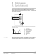
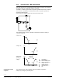
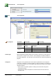
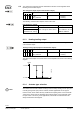
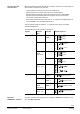
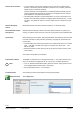
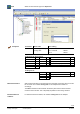
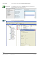
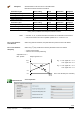
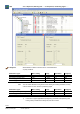
Table Of Contents
- RXB (KNX) applications library
- RXB Description of functions for FC10, FC11, FC12, FC13
- Table of contents
- 1 Introduction
- 2 Definitions / Tools
- 3 Select communication mode
- 4 Applications, parameters
- 5 Room operating modes
- 5.1 Description
- 5.2 Overview
- 5.3 Determine the room operating mode in Desigo (S-mode)
- 5.3.1 Local control of room operating mode via a window contact
- 5.3.2 Central control of room operating mode via input from the Use time schedule
- 5.3.3 Central and local control of room operating modebased on occupancy
- 5.3.4 Central control of room operating mode viathe Room operating mode time schedule
- 5.3.5 Local control of room operating mode with a room unit
- 5.3.6 Local control of room operating mode via the Temporary Comfort mode input
- 5.3.7 Effective room operating mode
- 5.3.8 Desigo examples
- 5.4 Determine the room operating mode with third-party products (S-mode)
- 5.4.1 Local control of room operating mode via the window contact input
- 5.4.2 Central control of room operating mode via the Room operating mode time schedule
- 5.4.3 Central control of room operating mode via the Use and Occupancy time schedules
- 5.4.4 Central and local control of room operating modebased on occupancy
- 5.4.5 Local control of room operating mode with a room unit
- 5.4.6 Local control of room operating mode via the Temporary Comfort mode input
- 5.4.7 Effective room operating mode
- 5.4.8 Third-party (S-mode) examples
- 5.5 Determine the room operating mode with Synco (LTE mode)
- 5.5.1 Local control of room operating mode via the window contact input
- 5.5.2 Central control of the room operating mode via Enable Comfort
- 5.5.3 Central control of room operating mode via Room operating mode input
- 5.5.4 Local control of room operating mode via presence detector
- 5.5.5 Local control of room operating mode with a room unit
- 5.5.6 LTE-Mode Examples
- 5.6 Determine the room operating mode without a bus (stand-alone)
- 6 Setpoint calculation
- 7 Temperature measurement
- 8 Control sequences
- 9 Fan control
- 10 Master/slave
- 11 General and central functions
- 11.1 Send heartbeat and receive timeouts
- 11.2 Digital inputs
- 11.3 Temporary Comfort mode
- 11.4 Presence detector switch-on and switchoff delay
- 11.5 Heating and cooling demand
- 11.6 Heating/cooling signal output
- 11.7 Special functions
- 11.8 Boost heating (Morning Warmup, 2)
- 11.9 Night purge (Night Purge, 4), (FNC10, FNC12)
- 11.10 Precooling (Precool, 5)
- 11.11 Test mode (Test, 7)
- 11.12 Emergency heating (Emergency Heat, 8)
- 11.13 Rapid ventilation (Fan only, 9)
- 11.14 Free cooling (Freecool, 10)
- 11.15 Alarm
- 11.16 Reset the setpoint shift
- 11.17 Free inputs/outputs
- 11.18 Software version
- 11.19 Device state
- 12 Room unit
- 13 KNX information
- 14 FAQs
- 15 Integrate RXB in Desigo/Synco
- 15.1 Case 1: Integration into Synco
- 15.2 Case 2: Integration into Desigo
- 15.3 Case 3: Display in Desigo, with shared Synco time scheduler
- 15.4 Case 4: Display in Desigo/Synco, with shared Synco time scheduler
- 15.5 Case 5: Display in Desigo, andseparate time schedulers
- 15.6 Case 6: Separate display, andseparate time schedulers
- 15.7 Case 7: Separate display, andshared Synco time scheduler
- 16 Working with different tools

86/182
Siemens RXB (KNX) application library RXB Description of functions for FC-10, FC-11, FC-12, FC-13 CM110385en_08
Building Technologies Control sequences 2013-06-17
• It is not possible to ensure exact parallel running of more than one thermal valve
actuator. If several fan-coils are controlled by the same room controller, preference
should be given to motorized actuators.
If thermal actuators must nevertheless be controlled in parallel, third-party thermal
must be parameterized regardless of manufacture. This applies also if an external
power amplifier is used to drive the actuators.
• Thermal actuators operate at a raised temperature. To ensure a fast response, the
actuators are continuously preheated to a slightly higher temperature (5% – 1 s ON /
19 s OFF). They therefore continue to receive pulses from the controller even when
closed.
Möhlenhoff actuators have been tested successfully in our HVAC laboratory.
Electromechanical third-party devices often have different runtimes for opening and
closing. For optimal control, the longer of the two running times must be parameterized.
When switching on the controller, after parameterization, after switching from test mode
to normal mode and for valve protection (unblocking, see page 92), the actuators are
synchronized:
• Thermal heating and cooling valve actuators are controlled with "Open" for 5 minutes
(50% – 1 sec ON/ 1 sec OFF), then again for 5 minutes with "Close" (5% – 1 sec
ON/ 19 sec OFF).
• Motorized actuators are first opened (110% of the runtime) and then closed (110%
of the runtime).
The sequence starts after synchronization.
The RXB39.1 is designed for running proportional (DC 0…10 V) valve actuators (YC1 /
YC2). The actuators are supplied wit AC 24 V by the room controller (terminal G).
• In FC-13, FNC04 and FNC08 the heating sequence and the cooling sequence have
to be equipped with the same actuator / valve types.
• No synchronization for DC 0...10 V actuators.
The actuator type used must be defined at the engineering stage:
Select Sequences:
Thermal valve actuators
Thermal third party
devices
Electromechanical third-
party devices
Synchronize
Proportional actuators
STOP
Note!
Parameterization
ETS Professional