
Operating Instructions
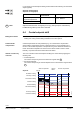
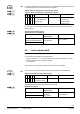
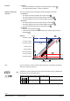
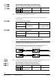
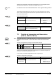
Table Of Contents
- RXB (KNX) applications library
- RXB Description of functions for FC10, FC11, FC12, FC13
- Table of contents
- 1 Introduction
- 2 Definitions / Tools
- 3 Select communication mode
- 4 Applications, parameters
- 5 Room operating modes
- 5.1 Description
- 5.2 Overview
- 5.3 Determine the room operating mode in Desigo (S-mode)
- 5.3.1 Local control of room operating mode via a window contact
- 5.3.2 Central control of room operating mode via input from the Use time schedule
- 5.3.3 Central and local control of room operating modebased on occupancy
- 5.3.4 Central control of room operating mode viathe Room operating mode time schedule
- 5.3.5 Local control of room operating mode with a room unit
- 5.3.6 Local control of room operating mode via the Temporary Comfort mode input
- 5.3.7 Effective room operating mode
- 5.3.8 Desigo examples
- 5.4 Determine the room operating mode with third-party products (S-mode)
- 5.4.1 Local control of room operating mode via the window contact input
- 5.4.2 Central control of room operating mode via the Room operating mode time schedule
- 5.4.3 Central control of room operating mode via the Use and Occupancy time schedules
- 5.4.4 Central and local control of room operating modebased on occupancy
- 5.4.5 Local control of room operating mode with a room unit
- 5.4.6 Local control of room operating mode via the Temporary Comfort mode input
- 5.4.7 Effective room operating mode
- 5.4.8 Third-party (S-mode) examples
- 5.5 Determine the room operating mode with Synco (LTE mode)
- 5.5.1 Local control of room operating mode via the window contact input
- 5.5.2 Central control of the room operating mode via Enable Comfort
- 5.5.3 Central control of room operating mode via Room operating mode input
- 5.5.4 Local control of room operating mode via presence detector
- 5.5.5 Local control of room operating mode with a room unit
- 5.5.6 LTE-Mode Examples
- 5.6 Determine the room operating mode without a bus (stand-alone)
- 6 Setpoint calculation
- 7 Temperature measurement
- 8 Control sequences
- 9 Fan control
- 10 Master/slave
- 11 General and central functions
- 11.1 Send heartbeat and receive timeouts
- 11.2 Digital inputs
- 11.3 Temporary Comfort mode
- 11.4 Presence detector switch-on and switchoff delay
- 11.5 Heating and cooling demand
- 11.6 Heating/cooling signal output
- 11.7 Special functions
- 11.8 Boost heating (Morning Warmup, 2)
- 11.9 Night purge (Night Purge, 4), (FNC10, FNC12)
- 11.10 Precooling (Precool, 5)
- 11.11 Test mode (Test, 7)
- 11.12 Emergency heating (Emergency Heat, 8)
- 11.13 Rapid ventilation (Fan only, 9)
- 11.14 Free cooling (Freecool, 10)
- 11.15 Alarm
- 11.16 Reset the setpoint shift
- 11.17 Free inputs/outputs
- 11.18 Software version
- 11.19 Device state
- 12 Room unit
- 13 KNX information
- 14 FAQs
- 15 Integrate RXB in Desigo/Synco
- 15.1 Case 1: Integration into Synco
- 15.2 Case 2: Integration into Desigo
- 15.3 Case 3: Display in Desigo, with shared Synco time scheduler
- 15.4 Case 4: Display in Desigo/Synco, with shared Synco time scheduler
- 15.5 Case 5: Display in Desigo, andseparate time schedulers
- 15.6 Case 6: Separate display, andseparate time schedulers
- 15.7 Case 7: Separate display, andshared Synco time scheduler
- 16 Working with different tools

79/182
Siemens RXB (KNX) application library RXB Description of functions for FC-10, FC-11, FC-12, FC-13 CM110385en_08
Building Technologies Temperature measurement 2013-06-17
Subject to the appropriate configuration and integration, the room temperature/return
air temperature is read by the controller immediately after a reset.
For a Konnex sensor the send heartbeat must be set to "Cyclical sending enabled"
The situation is slightly different in LTE mode: Here, each signal has its own specific
name, and the room temperature and return air temperature therefore each have their
own communication object.
Room temperature (Input)
Possible partner function blocks
Known partner devices
TempRoom
321 RTS
Room Temperature Sensor
Siemens:
Synco RMH760
RMU710 / 20 / 30
QAW740
Geographical zone
Return air temperature (Input)
Possible partner function blocks
Known partner devices
TempReturnAir
323 RNATS
Return Air Temperature Sensor
---
Geographical zone
7.2 Outside air temperature via Konnex bus
(FNC10, FNC12, FNC18)
For the FNC10, FNC12, and FNC18 applications, the outside air temperature must be
available as a bus information. It can be read via the next S-mode communication
object:
Outside air temperature input (Input communication object)
Flags
Type Receive timeout
Value
R
W
C
T
U
0 1 1 1 1 9.001
DPT_Value_Temp
yes Floating point (°C)
Subject to the appropriate configuration and integration, the outside air temperature is
read by the controller immediately after a reset.
In LTE mode, the outside air temperature is sent in a special zone.
Outside air temperature input (Input)
Possible partner function blocks
Known partner devices
TempOutside
320 OTS
Room Temperature Sensor
Siemens:
Synco RMH760
RMU710 / 20 / 30
RMB795 / RMS705
Outside air
temperature zone
STOP
Note!
CO