
Operating Instructions
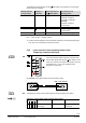
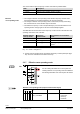
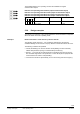
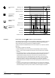
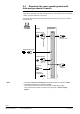
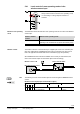
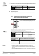
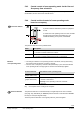
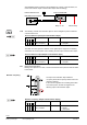
Table Of Contents
- RXB (KNX) applications library
- RXB Description of functions for FC10, FC11, FC12, FC13
- Table of contents
- 1 Introduction
- 2 Definitions / Tools
- 3 Select communication mode
- 4 Applications, parameters
- 5 Room operating modes
- 5.1 Description
- 5.2 Overview
- 5.3 Determine the room operating mode in Desigo (S-mode)
- 5.3.1 Local control of room operating mode via a window contact
- 5.3.2 Central control of room operating mode via input from the Use time schedule
- 5.3.3 Central and local control of room operating modebased on occupancy
- 5.3.4 Central control of room operating mode viathe Room operating mode time schedule
- 5.3.5 Local control of room operating mode with a room unit
- 5.3.6 Local control of room operating mode via the Temporary Comfort mode input
- 5.3.7 Effective room operating mode
- 5.3.8 Desigo examples
- 5.4 Determine the room operating mode with third-party products (S-mode)
- 5.4.1 Local control of room operating mode via the window contact input
- 5.4.2 Central control of room operating mode via the Room operating mode time schedule
- 5.4.3 Central control of room operating mode via the Use and Occupancy time schedules
- 5.4.4 Central and local control of room operating modebased on occupancy
- 5.4.5 Local control of room operating mode with a room unit
- 5.4.6 Local control of room operating mode via the Temporary Comfort mode input
- 5.4.7 Effective room operating mode
- 5.4.8 Third-party (S-mode) examples
- 5.5 Determine the room operating mode with Synco (LTE mode)
- 5.5.1 Local control of room operating mode via the window contact input
- 5.5.2 Central control of the room operating mode via Enable Comfort
- 5.5.3 Central control of room operating mode via Room operating mode input
- 5.5.4 Local control of room operating mode via presence detector
- 5.5.5 Local control of room operating mode with a room unit
- 5.5.6 LTE-Mode Examples
- 5.6 Determine the room operating mode without a bus (stand-alone)
- 6 Setpoint calculation
- 7 Temperature measurement
- 8 Control sequences
- 9 Fan control
- 10 Master/slave
- 11 General and central functions
- 11.1 Send heartbeat and receive timeouts
- 11.2 Digital inputs
- 11.3 Temporary Comfort mode
- 11.4 Presence detector switch-on and switchoff delay
- 11.5 Heating and cooling demand
- 11.6 Heating/cooling signal output
- 11.7 Special functions
- 11.8 Boost heating (Morning Warmup, 2)
- 11.9 Night purge (Night Purge, 4), (FNC10, FNC12)
- 11.10 Precooling (Precool, 5)
- 11.11 Test mode (Test, 7)
- 11.12 Emergency heating (Emergency Heat, 8)
- 11.13 Rapid ventilation (Fan only, 9)
- 11.14 Free cooling (Freecool, 10)
- 11.15 Alarm
- 11.16 Reset the setpoint shift
- 11.17 Free inputs/outputs
- 11.18 Software version
- 11.19 Device state
- 12 Room unit
- 13 KNX information
- 14 FAQs
- 15 Integrate RXB in Desigo/Synco
- 15.1 Case 1: Integration into Synco
- 15.2 Case 2: Integration into Desigo
- 15.3 Case 3: Display in Desigo, with shared Synco time scheduler
- 15.4 Case 4: Display in Desigo/Synco, with shared Synco time scheduler
- 15.5 Case 5: Display in Desigo, andseparate time schedulers
- 15.6 Case 6: Separate display, andseparate time schedulers
- 15.7 Case 7: Separate display, andshared Synco time scheduler
- 16 Working with different tools

42/182
Siemens RXB (KNX) application library RXB Description of functions for FC-10, FC-11, FC-12, FC-13 CM110385en_08
Building Technologies Room operating modes 2013-06-17
The communication object Temporary Comfort mode has two possible states:
State Description
1 = Trigger
Effective room operating mode is Comfort
0 = Not used
Has no effect on the Effective room operating mode
• The change of effective room operating mode with the Temporary Comfort mode
during the building-in-use period (defined by the Use time schedule)
• The change of effective room operating mode is event-driven, the key factor being
the moment when the communication object is received.
• The Effective occupancy or room unit (both Priority 3) can cause the effective room
operating mode to change again the last command always applies.
The table below shows the effect of the Temporary Comfort mode on the effective room
operating mode of the room controller.
Existing effective
room op. mode
Temporary
Comfort mode
New effective room operating
mode
Comfort
0 = Not used
No effect
Precomfort
1 = Trigger
Comfort
Economy
1 = Trigger
Comfort during Temporary Comfort
period
1)
Protection mode
1 = Trigger
Protection, no change
Key: 1 means: "changes to 1"
1) Comfort mode is operative for the pre-defined Temporary Comfort period (see page
143). The room controller then reverts to Economy.
5.3.7 Effective room operating mode
CO
S
Central Local
1.
2.
3.
S
DI
S
S
S
DI
S
3.
Controller
Prio
PPS2
3.
S
For the building automation and control system the
resulting effective room operating mode is available to
the building automation and control system as follows:
Effective room operating mode (Output communication object)
Flags
Type
Send heartbeat
States
R
W
C
T
U
1 0 1 1 0 20.102
DPT_HVACMode
Yes
1 = Comfort
2 = Precomfort
3 = Economy
4 = Protection
Effective
room operating mode