
Operating Instructions
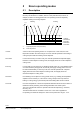
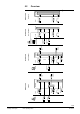
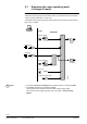
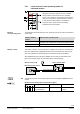
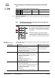
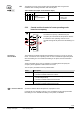
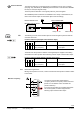
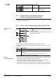
Table Of Contents
- RXB (KNX) applications library
- RXB Description of functions for FC10, FC11, FC12, FC13
- Table of contents
- 1 Introduction
- 2 Definitions / Tools
- 3 Select communication mode
- 4 Applications, parameters
- 5 Room operating modes
- 5.1 Description
- 5.2 Overview
- 5.3 Determine the room operating mode in Desigo (S-mode)
- 5.3.1 Local control of room operating mode via a window contact
- 5.3.2 Central control of room operating mode via input from the Use time schedule
- 5.3.3 Central and local control of room operating modebased on occupancy
- 5.3.4 Central control of room operating mode viathe Room operating mode time schedule
- 5.3.5 Local control of room operating mode with a room unit
- 5.3.6 Local control of room operating mode via the Temporary Comfort mode input
- 5.3.7 Effective room operating mode
- 5.3.8 Desigo examples
- 5.4 Determine the room operating mode with third-party products (S-mode)
- 5.4.1 Local control of room operating mode via the window contact input
- 5.4.2 Central control of room operating mode via the Room operating mode time schedule
- 5.4.3 Central control of room operating mode via the Use and Occupancy time schedules
- 5.4.4 Central and local control of room operating modebased on occupancy
- 5.4.5 Local control of room operating mode with a room unit
- 5.4.6 Local control of room operating mode via the Temporary Comfort mode input
- 5.4.7 Effective room operating mode
- 5.4.8 Third-party (S-mode) examples
- 5.5 Determine the room operating mode with Synco (LTE mode)
- 5.5.1 Local control of room operating mode via the window contact input
- 5.5.2 Central control of the room operating mode via Enable Comfort
- 5.5.3 Central control of room operating mode via Room operating mode input
- 5.5.4 Local control of room operating mode via presence detector
- 5.5.5 Local control of room operating mode with a room unit
- 5.5.6 LTE-Mode Examples
- 5.6 Determine the room operating mode without a bus (stand-alone)
- 6 Setpoint calculation
- 7 Temperature measurement
- 8 Control sequences
- 9 Fan control
- 10 Master/slave
- 11 General and central functions
- 11.1 Send heartbeat and receive timeouts
- 11.2 Digital inputs
- 11.3 Temporary Comfort mode
- 11.4 Presence detector switch-on and switchoff delay
- 11.5 Heating and cooling demand
- 11.6 Heating/cooling signal output
- 11.7 Special functions
- 11.8 Boost heating (Morning Warmup, 2)
- 11.9 Night purge (Night Purge, 4), (FNC10, FNC12)
- 11.10 Precooling (Precool, 5)
- 11.11 Test mode (Test, 7)
- 11.12 Emergency heating (Emergency Heat, 8)
- 11.13 Rapid ventilation (Fan only, 9)
- 11.14 Free cooling (Freecool, 10)
- 11.15 Alarm
- 11.16 Reset the setpoint shift
- 11.17 Free inputs/outputs
- 11.18 Software version
- 11.19 Device state
- 12 Room unit
- 13 KNX information
- 14 FAQs
- 15 Integrate RXB in Desigo/Synco
- 15.1 Case 1: Integration into Synco
- 15.2 Case 2: Integration into Desigo
- 15.3 Case 3: Display in Desigo, with shared Synco time scheduler
- 15.4 Case 4: Display in Desigo/Synco, with shared Synco time scheduler
- 15.5 Case 5: Display in Desigo, andseparate time schedulers
- 15.6 Case 6: Separate display, andseparate time schedulers
- 15.7 Case 7: Separate display, andshared Synco time scheduler
- 16 Working with different tools

36/182
Siemens RXB (KNX) application library RXB Description of functions for FC-10, FC-11, FC-12, FC-13 CM110385en_08
Building Technologies Room operating modes 2013-06-17
The state of the room controller (result of the logic OR operation) is mapped to the
building automation and control system via the following S-mode communication
object:
Window contact output (Output communication object)
Flags
Type
Send heartbeat
States
R
W
C
T
U
1 0 1 1 0 1.019
DPT_WindowDoor
Yes 0 = Closed
1 = Open
Master/slave applications
Bindings are required in S-mode, in order to transmit the slave window contact status to
the master.
5.3.2 Central control of room operating mode via input from
the Use time schedule
S
Central Local
1.
2.
3.
S
DI
S
S
S
DI
S
3.
Controller
Prio
PPS2
3.
S
This time schedule determines the overall period of
time for which the entire building is in use. Typically,
this schedule is used for night setback throughout
the building, or for longer periods when the building
is not in use.
Outside the “building-in-use” times, inputs from
3
rd
priority sources are disabled. This prevents
demand signals from being sent to the primary plant
when, for example, a security guard enters a room.
The table below shows the three possible occupancy states and the resulting effective
room operating mode.
Switch state Description Effective room op. mode
Building in use • Full availability of all plant
• Building enabled for use
• Inputs of priority 3 are enabled (Occupancy time
schedule, presence detector, room unit, and
Temporary Comfort mode)
As defined by Occupancy
time schedule, presence
detector or room unit
Building not in use • Reduced availability of plant
• Inputs of priority 3 are disabled (Occupancy time
schedule, presence detector, room unit, and
Temporary Comfort mode)
• Application:
Building temporarily not in use
The building must reach the Comfort
temperature within hours
Economy
Building protection • Setpoints reduced to the minimum necessary to
protect the building fabric.
• Inputs of priority 3 are disabled (Occupancy time
schedule, presence detector, room unit, and
Temporary Comfort mode)
• Application:
Longer periods of non-use of the building
Protection mode
CO
Note
Effective
room operating mode