
Operating Instructions
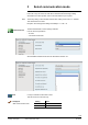
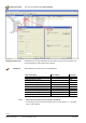
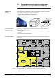
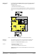
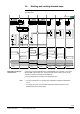
Table Of Contents
- RXB (KNX) applications library
- RXB Description of functions for FC10, FC11, FC12, FC13
- Table of contents
- 1 Introduction
- 2 Definitions / Tools
- 3 Select communication mode
- 4 Applications, parameters
- 5 Room operating modes
- 5.1 Description
- 5.2 Overview
- 5.3 Determine the room operating mode in Desigo (S-mode)
- 5.3.1 Local control of room operating mode via a window contact
- 5.3.2 Central control of room operating mode via input from the Use time schedule
- 5.3.3 Central and local control of room operating modebased on occupancy
- 5.3.4 Central control of room operating mode viathe Room operating mode time schedule
- 5.3.5 Local control of room operating mode with a room unit
- 5.3.6 Local control of room operating mode via the Temporary Comfort mode input
- 5.3.7 Effective room operating mode
- 5.3.8 Desigo examples
- 5.4 Determine the room operating mode with third-party products (S-mode)
- 5.4.1 Local control of room operating mode via the window contact input
- 5.4.2 Central control of room operating mode via the Room operating mode time schedule
- 5.4.3 Central control of room operating mode via the Use and Occupancy time schedules
- 5.4.4 Central and local control of room operating modebased on occupancy
- 5.4.5 Local control of room operating mode with a room unit
- 5.4.6 Local control of room operating mode via the Temporary Comfort mode input
- 5.4.7 Effective room operating mode
- 5.4.8 Third-party (S-mode) examples
- 5.5 Determine the room operating mode with Synco (LTE mode)
- 5.5.1 Local control of room operating mode via the window contact input
- 5.5.2 Central control of the room operating mode via Enable Comfort
- 5.5.3 Central control of room operating mode via Room operating mode input
- 5.5.4 Local control of room operating mode via presence detector
- 5.5.5 Local control of room operating mode with a room unit
- 5.5.6 LTE-Mode Examples
- 5.6 Determine the room operating mode without a bus (stand-alone)
- 6 Setpoint calculation
- 7 Temperature measurement
- 8 Control sequences
- 9 Fan control
- 10 Master/slave
- 11 General and central functions
- 11.1 Send heartbeat and receive timeouts
- 11.2 Digital inputs
- 11.3 Temporary Comfort mode
- 11.4 Presence detector switch-on and switchoff delay
- 11.5 Heating and cooling demand
- 11.6 Heating/cooling signal output
- 11.7 Special functions
- 11.8 Boost heating (Morning Warmup, 2)
- 11.9 Night purge (Night Purge, 4), (FNC10, FNC12)
- 11.10 Precooling (Precool, 5)
- 11.11 Test mode (Test, 7)
- 11.12 Emergency heating (Emergency Heat, 8)
- 11.13 Rapid ventilation (Fan only, 9)
- 11.14 Free cooling (Freecool, 10)
- 11.15 Alarm
- 11.16 Reset the setpoint shift
- 11.17 Free inputs/outputs
- 11.18 Software version
- 11.19 Device state
- 12 Room unit
- 13 KNX information
- 14 FAQs
- 15 Integrate RXB in Desigo/Synco
- 15.1 Case 1: Integration into Synco
- 15.2 Case 2: Integration into Desigo
- 15.3 Case 3: Display in Desigo, with shared Synco time scheduler
- 15.4 Case 4: Display in Desigo/Synco, with shared Synco time scheduler
- 15.5 Case 5: Display in Desigo, andseparate time schedulers
- 15.6 Case 6: Separate display, andseparate time schedulers
- 15.7 Case 7: Separate display, andshared Synco time scheduler
- 16 Working with different tools

28/182
Siemens RXB (KNX) application library RXB Description of functions for FC-10, FC-11, FC-12, FC-13 CM110385en_08
Building Technologies Select communication mode 2013-06-17
3.3 Implementation of application example
Using the "C3127_Planning and Commissioning Report, Communication Synco 700",
the plant and the required communication settings can be represented in an easy-to-
understand way.
Proceed as follows:
1. Enter general information, such as plant name, device names, device types,
applications, etc.
2. Transfer the device addresses of all bus users and the basic settings of
communication from the floor plan.
3. Enter the "Geographical zone addresses" in agreement with the group formations
made.
The following illustration shows the completed report for the plant of Sport Ltd:
Possible settings RMU RMH RMK OZW RMB RXB QAW 1 2 3 4 5 6 7
Plant Sport Ltd Sport Ltd Sport Ltd Sport Ltd Sport Ltd Sport Ltd Sport Ltd
Room number 309 307 308 308 308
Device name X X X - X X - Reception Conference Reception Office Office Office Office
Device type
RMU
7..
RMH,
RMZ
RMK
OZW
771...
RMB
795
RXB
....
QAW
740
RMB795 RXB.. RMB795 [2] RXB.. RXB.. RXB.. RXB..
Plant type X X X - X X - B FC03 FC03 FC03 FC03 FC03
KNX-ID (Example ID: 00FD000016D5) X X X X X X X
Area [ 0...15 ] . Line [ 1; 2...15 ] .
Device address [1..253;255]
X X X X X X X 0.2.10 0.2.114 0.2.110 0.2.111 0.2.112 0.2.113
Decentral bus power supply [ Off, On ] X X X - X - - Aus
Clock time operation [ Autonomous, Slave, Master ] X X X X X - - Autonom
Remote setting chlock slave [ No, Yes ] X X X X X - - Nein
Remote reset of fault [ No, Yes ] X X X - X - - Nein
Geographical zone (Apartment
.Room
.Subzone)
(A.R.S) [ 1...126 ].[ 1...63 ]. [1]
X
2
2X X - 10X X.X.1 X 1.1.1 1.1.1 2.1.1 2.1.1 2.2.1 2.3.1 2.4.1
(with own room sensor)
X
1
2X X - - X X X ---- X X X
Time switch operation [ Autonomous, Slave, Master ]
X
1
2X X - - - -
Time switch slave (apartment
) [ 1...126 ] . 1 . 1
X
1
2X X - - X.1.1 - 1.1.1 2.1.1 2.1.1 2.1.1 2.1.1
Temperature control [ Master, Slave ] - - - - - X - Master Master Master Master Master
* Control strategy [ Caskade, Constant, Alternating ]
X
4
- - - - - -
** Combination of room control [ Master,
Slave external setpoint , Slave internal setpoint ]
- 2X X - - - -
Room group (name)
- - - -
10X - - Conference Office
QAW operation zone (apartment
) [ ---,1...126 ] . 1 . 1
- - - -
10X - -
Information
Room /
Room group
Basic settings
Room group Conference
Apartment = 1
Room group Office
Apartment = 2
1
2
3
In agreement with the list created, the settings of the data points with the same names
are to be made on the devices during commissioning.
Procedure for
engineering
Example Sport Ltd
Implementation with
commissioning