
Operating Instructions
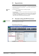
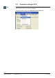
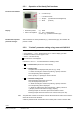
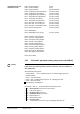
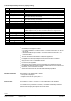
Table Of Contents
- RXB (KNX) applications library
- RXB Description of functions for FC10, FC11, FC12, FC13
- Table of contents
- 1 Introduction
- 2 Definitions / Tools
- 3 Select communication mode
- 4 Applications, parameters
- 5 Room operating modes
- 5.1 Description
- 5.2 Overview
- 5.3 Determine the room operating mode in Desigo (S-mode)
- 5.3.1 Local control of room operating mode via a window contact
- 5.3.2 Central control of room operating mode via input from the Use time schedule
- 5.3.3 Central and local control of room operating modebased on occupancy
- 5.3.4 Central control of room operating mode viathe Room operating mode time schedule
- 5.3.5 Local control of room operating mode with a room unit
- 5.3.6 Local control of room operating mode via the Temporary Comfort mode input
- 5.3.7 Effective room operating mode
- 5.3.8 Desigo examples
- 5.4 Determine the room operating mode with third-party products (S-mode)
- 5.4.1 Local control of room operating mode via the window contact input
- 5.4.2 Central control of room operating mode via the Room operating mode time schedule
- 5.4.3 Central control of room operating mode via the Use and Occupancy time schedules
- 5.4.4 Central and local control of room operating modebased on occupancy
- 5.4.5 Local control of room operating mode with a room unit
- 5.4.6 Local control of room operating mode via the Temporary Comfort mode input
- 5.4.7 Effective room operating mode
- 5.4.8 Third-party (S-mode) examples
- 5.5 Determine the room operating mode with Synco (LTE mode)
- 5.5.1 Local control of room operating mode via the window contact input
- 5.5.2 Central control of the room operating mode via Enable Comfort
- 5.5.3 Central control of room operating mode via Room operating mode input
- 5.5.4 Local control of room operating mode via presence detector
- 5.5.5 Local control of room operating mode with a room unit
- 5.5.6 LTE-Mode Examples
- 5.6 Determine the room operating mode without a bus (stand-alone)
- 6 Setpoint calculation
- 7 Temperature measurement
- 8 Control sequences
- 9 Fan control
- 10 Master/slave
- 11 General and central functions
- 11.1 Send heartbeat and receive timeouts
- 11.2 Digital inputs
- 11.3 Temporary Comfort mode
- 11.4 Presence detector switch-on and switchoff delay
- 11.5 Heating and cooling demand
- 11.6 Heating/cooling signal output
- 11.7 Special functions
- 11.8 Boost heating (Morning Warmup, 2)
- 11.9 Night purge (Night Purge, 4), (FNC10, FNC12)
- 11.10 Precooling (Precool, 5)
- 11.11 Test mode (Test, 7)
- 11.12 Emergency heating (Emergency Heat, 8)
- 11.13 Rapid ventilation (Fan only, 9)
- 11.14 Free cooling (Freecool, 10)
- 11.15 Alarm
- 11.16 Reset the setpoint shift
- 11.17 Free inputs/outputs
- 11.18 Software version
- 11.19 Device state
- 12 Room unit
- 13 KNX information
- 14 FAQs
- 15 Integrate RXB in Desigo/Synco
- 15.1 Case 1: Integration into Synco
- 15.2 Case 2: Integration into Desigo
- 15.3 Case 3: Display in Desigo, with shared Synco time scheduler
- 15.4 Case 4: Display in Desigo/Synco, with shared Synco time scheduler
- 15.5 Case 5: Display in Desigo, andseparate time schedulers
- 15.6 Case 6: Separate display, andseparate time schedulers
- 15.7 Case 7: Separate display, andshared Synco time scheduler
- 16 Working with different tools

20/182
Siemens RXB (KNX) application library RXB Description of functions for FC-10, FC-11, FC-12, FC-13 CM110385en_08
Building Technologies Definitions / Tools 2013-06-17
Theoretically possible positions for periphery testing:
T 01
Sensor input B1
9)
Value of B1 in °C.
T 11
Digital input D1
9)
True state of the contact at D1 (0 = open; 1 = closed).
T 12
Digital input D2
9)
True state of the contact at D2 (0 = open; 1 = closed).
T 21
Heating valve
1)
2)
7)
8)
By considering the configuration (proportional; 100 = 100% pos. signal).
(Also applies to damper in FNC20).
T 22
Cooling valve
1)
2)
7)
8)
By considering the configuration (proportional; 100 = 100% pos. signal).
(Also applies to damper in FNC20).
T 23
El. Heating register
3)
7)
Pulse to the electric register (value > 0
10 s pulse).
T 25
Heating surface
1)
4) 7)
By considering the configuration (proportional; 100 = 100% pos. signal).
T 27
Damper
1)
4)
7)
By considering the configuration (proportional; 100 = 100% pos. signal).
T 31
Fan relay
RXB2...: Speed control (%-value converted to speeds).
RXB39.1: Speed control (%-value converted to DC 0...10 V signal on YC3)
T 41
Relay Q14
6)
(0 = Relay deenergized; 1 = energized).
T 42
Relay Q24
6)
(0 = Relay deenergized; 1 = energized).
T 43
Relay Q34
6)
(0 = Relay deenergized; 1 = energized).
T 51
Triac Y1
6)
(0 = Triac disabled; 1 = enabled).
T 52
Triac Y1
6)
(0 = Triac disabled; 1 = enabled).
T 53
Triac Y3
6)
(0 = Triac disabled; 1 = enabled).
T 54
Triac Y4
6)
(0 = Triac disabled; 1 = enabled).
1)
Considering the configuration means:
– For thermal actuators, the output is clocked 1:1 during the first 400 s, then as per
the % entry.
– Motorized actuators open at 100% 1.5 times the runtime, and close at 0% 1.5
times the runtime.
2)
T21 and T22 have the same effect in changeover applications.
3)
Only for RXB22.1/FC-12 and RXB39.1/FC-13
If a digital input is used by a safety thermostat, the thermostat is considered.
4)
Only for RXB21.1/FC-11 and RXB24.1/CC-02.
6)
If not used by the application.
7)
Only the I/Os of the controller and no bus actuators are controlled in test mode.
8)
For FNC20, the different damper runtimes for heatin/cooling are not considered; for
test mode, the sum of the times are halved
9)
Values are correct when read, but will not automatically be updated.
The positions can be selected with < (Enter).
• The inputs are displayed
• Outputs can be set via < (Enter) and + / –.
To exit test mode, press >- (Escape) 2 - 3 times (depending on the situation).
If no further button is pressed for 5 minutes, the controller automatically reassumes
Normal mode and all physical outputs are switched back.
Monitor and operate
Exit test mode