
Operating Instructions
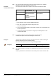
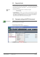
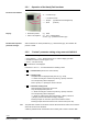
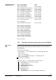
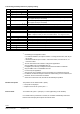
Table Of Contents
- RXB (KNX) applications library
- RXB Description of functions for FC10, FC11, FC12, FC13
- Table of contents
- 1 Introduction
- 2 Definitions / Tools
- 3 Select communication mode
- 4 Applications, parameters
- 5 Room operating modes
- 5.1 Description
- 5.2 Overview
- 5.3 Determine the room operating mode in Desigo (S-mode)
- 5.3.1 Local control of room operating mode via a window contact
- 5.3.2 Central control of room operating mode via input from the Use time schedule
- 5.3.3 Central and local control of room operating modebased on occupancy
- 5.3.4 Central control of room operating mode viathe Room operating mode time schedule
- 5.3.5 Local control of room operating mode with a room unit
- 5.3.6 Local control of room operating mode via the Temporary Comfort mode input
- 5.3.7 Effective room operating mode
- 5.3.8 Desigo examples
- 5.4 Determine the room operating mode with third-party products (S-mode)
- 5.4.1 Local control of room operating mode via the window contact input
- 5.4.2 Central control of room operating mode via the Room operating mode time schedule
- 5.4.3 Central control of room operating mode via the Use and Occupancy time schedules
- 5.4.4 Central and local control of room operating modebased on occupancy
- 5.4.5 Local control of room operating mode with a room unit
- 5.4.6 Local control of room operating mode via the Temporary Comfort mode input
- 5.4.7 Effective room operating mode
- 5.4.8 Third-party (S-mode) examples
- 5.5 Determine the room operating mode with Synco (LTE mode)
- 5.5.1 Local control of room operating mode via the window contact input
- 5.5.2 Central control of the room operating mode via Enable Comfort
- 5.5.3 Central control of room operating mode via Room operating mode input
- 5.5.4 Local control of room operating mode via presence detector
- 5.5.5 Local control of room operating mode with a room unit
- 5.5.6 LTE-Mode Examples
- 5.6 Determine the room operating mode without a bus (stand-alone)
- 6 Setpoint calculation
- 7 Temperature measurement
- 8 Control sequences
- 9 Fan control
- 10 Master/slave
- 11 General and central functions
- 11.1 Send heartbeat and receive timeouts
- 11.2 Digital inputs
- 11.3 Temporary Comfort mode
- 11.4 Presence detector switch-on and switchoff delay
- 11.5 Heating and cooling demand
- 11.6 Heating/cooling signal output
- 11.7 Special functions
- 11.8 Boost heating (Morning Warmup, 2)
- 11.9 Night purge (Night Purge, 4), (FNC10, FNC12)
- 11.10 Precooling (Precool, 5)
- 11.11 Test mode (Test, 7)
- 11.12 Emergency heating (Emergency Heat, 8)
- 11.13 Rapid ventilation (Fan only, 9)
- 11.14 Free cooling (Freecool, 10)
- 11.15 Alarm
- 11.16 Reset the setpoint shift
- 11.17 Free inputs/outputs
- 11.18 Software version
- 11.19 Device state
- 12 Room unit
- 13 KNX information
- 14 FAQs
- 15 Integrate RXB in Desigo/Synco
- 15.1 Case 1: Integration into Synco
- 15.2 Case 2: Integration into Desigo
- 15.3 Case 3: Display in Desigo, with shared Synco time scheduler
- 15.4 Case 4: Display in Desigo/Synco, with shared Synco time scheduler
- 15.5 Case 5: Display in Desigo, andseparate time schedulers
- 15.6 Case 6: Separate display, andseparate time schedulers
- 15.7 Case 7: Separate display, andshared Synco time scheduler
- 16 Working with different tools

19/182
Siemens RXB (KNX) application library RXB Description of functions for FC-10, FC-11, FC-12, FC-13 CM110385en_08
Building Technologies Definitions / Tools 2013-06-17
If 4 or 5 is displayed, this mode can be selected via < (Enter).
The storage number (c1) is displayed and can be changed via + / – . Select the desired
storage (1...5) via < (Enter).
• If storage is empty, upload begins and the display flashes.
OK is displayed after successful upload.
• If the storage is full, "dEL" for "Delete?" is displayed.
Pressing <(Enter) at this time overwrites the existing set.
If you press > (Escape), the storage number which you can change via + / – is
displayed.
• If the parameter set does not match the connected controller, error
message "Err" is displayed.
Press > (Escape) to return to the storage number and select a different number.
• If the parameter set matches the connected controller, start download (display
flashes).
• If connected successfully, "P1" is displayed (see 2.5.2).
2.7 Test the periphery using room unit QAX34.3
This function requires a QAX34.3 with index D or higher!
The HandyTool allows you to test the connected field devices (sensors, actuators).
This works only for the controller with the connected HandyTool; it does not work in
master/slave mode.
An application must be selected and fully parameterized in the controller
(address and zones can contain default values).
Start parameterization mode:
• Press buttons < , > and – simultaneously for about 2 s until the display turns dark.
• Release the buttons.
• Press button – twice briefly.
• Press buttons + and – simultaneously for approx. 2s The display goes dark.
• Press button + twice briefly.
The display now shows
0 (mode 0).
Use + and / or – to choose between the following modes:
•
0 = Normal mode (normal room unit functions).
•
1 = Test mode
•
2 = Display mode (see 2.5.2).
•
3 = Parameterization mode (see 2.5.2
•
4 = Upload (see 2.6).
•
5 = Download (see 2.6).
•
6 = Service mode.
The following positions can be selected depending on the type of parameterization.
They are displayed with prefix "T".
The list shows all theoretically possible positions. However, only positions that are
available for selection based on the type of parameterization are displayed.
Uploading
Download
Prerequisite