
Operating Instructions
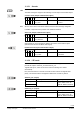
Table Of Contents
- RXB (KNX) applications library
- RXB Description of functions for FC10, FC11, FC12, FC13
- Table of contents
- 1 Introduction
- 2 Definitions / Tools
- 3 Select communication mode
- 4 Applications, parameters
- 5 Room operating modes
- 5.1 Description
- 5.2 Overview
- 5.3 Determine the room operating mode in Desigo (S-mode)
- 5.3.1 Local control of room operating mode via a window contact
- 5.3.2 Central control of room operating mode via input from the Use time schedule
- 5.3.3 Central and local control of room operating modebased on occupancy
- 5.3.4 Central control of room operating mode viathe Room operating mode time schedule
- 5.3.5 Local control of room operating mode with a room unit
- 5.3.6 Local control of room operating mode via the Temporary Comfort mode input
- 5.3.7 Effective room operating mode
- 5.3.8 Desigo examples
- 5.4 Determine the room operating mode with third-party products (S-mode)
- 5.4.1 Local control of room operating mode via the window contact input
- 5.4.2 Central control of room operating mode via the Room operating mode time schedule
- 5.4.3 Central control of room operating mode via the Use and Occupancy time schedules
- 5.4.4 Central and local control of room operating modebased on occupancy
- 5.4.5 Local control of room operating mode with a room unit
- 5.4.6 Local control of room operating mode via the Temporary Comfort mode input
- 5.4.7 Effective room operating mode
- 5.4.8 Third-party (S-mode) examples
- 5.5 Determine the room operating mode with Synco (LTE mode)
- 5.5.1 Local control of room operating mode via the window contact input
- 5.5.2 Central control of the room operating mode via Enable Comfort
- 5.5.3 Central control of room operating mode via Room operating mode input
- 5.5.4 Local control of room operating mode via presence detector
- 5.5.5 Local control of room operating mode with a room unit
- 5.5.6 LTE-Mode Examples
- 5.6 Determine the room operating mode without a bus (stand-alone)
- 6 Setpoint calculation
- 7 Temperature measurement
- 8 Control sequences
- 9 Fan control
- 10 Master/slave
- 11 General and central functions
- 11.1 Send heartbeat and receive timeouts
- 11.2 Digital inputs
- 11.3 Temporary Comfort mode
- 11.4 Presence detector switch-on and switchoff delay
- 11.5 Heating and cooling demand
- 11.6 Heating/cooling signal output
- 11.7 Special functions
- 11.8 Boost heating (Morning Warmup, 2)
- 11.9 Night purge (Night Purge, 4), (FNC10, FNC12)
- 11.10 Precooling (Precool, 5)
- 11.11 Test mode (Test, 7)
- 11.12 Emergency heating (Emergency Heat, 8)
- 11.13 Rapid ventilation (Fan only, 9)
- 11.14 Free cooling (Freecool, 10)
- 11.15 Alarm
- 11.16 Reset the setpoint shift
- 11.17 Free inputs/outputs
- 11.18 Software version
- 11.19 Device state
- 12 Room unit
- 13 KNX information
- 14 FAQs
- 15 Integrate RXB in Desigo/Synco
- 15.1 Case 1: Integration into Synco
- 15.2 Case 2: Integration into Desigo
- 15.3 Case 3: Display in Desigo, with shared Synco time scheduler
- 15.4 Case 4: Display in Desigo/Synco, with shared Synco time scheduler
- 15.5 Case 5: Display in Desigo, andseparate time schedulers
- 15.6 Case 6: Separate display, andseparate time schedulers
- 15.7 Case 7: Separate display, andshared Synco time scheduler
- 16 Working with different tools

160/182
Siemens RXB (KNX) application library RXB Description of functions for FC-10, FC-11, FC-12, FC-13 CM110385en_08
Building Technologies KNX information 2013-06-17
13 KNX information
13.1 Reset and startup response
A reset is initiated under the following circumstances:
• Processor failure(e.g. watchdog).
• After a power failure.
• After a bus power failure.
• Upon completion of a self test (using the communication object "StatusRequest").
• Via ETS (without a startup delay):
– After the download of the physical address.
– After the download of the parameters.
– Via ETS (menu Commissioning, Reset).
• After parameter setting in ACS.
• After leaving the parameter setting mode in the HandyTool.
• After test with the HandyTool.
The application is restarted after every reset. Depending on the controller address, this
may take 1...255 s.
Then, the bus connection is opened and all connected valve actuators are
synchronized. This takes the following time depending on application and actuator type:
– Typically 170 s for closing (runtime + 10%) for motorized actuators.
– 300 s ON and 300 s OFF (3rd party: 400 + 400 s) for thermal actuators.
The application is placed in a safe state. Any outputs that are not synchronized are not
operated (triac and DC 0...10 V outputs = 0, and relays = open).
Normal operation is resumed after synchronization.
When the controller exits the test mode, only a soft reset is carried out:
– The control algorithm, but not the complete application, is restarted.
– The 3-position valve and damper actuators are synchronized.
• 3-position actuators: Each time the control sequence reaches 0% or 100%, a limit
position synchronization takes place:
– For motorized actuators close or open during (runtime + 10%).
– For thermal actuators 300 s ON and 300 s OFF (3rd party: 400 s).
13.2 LED flashing pattern
An LED is located at the controller's bottom right indicating the operating state by
various flashing patterns:
Green, flashing
Normal operation.
Red, flashing
Programming mode for address assignment (ETS / ACS).
Orange / green,
flashing
• Startup phase (see above 13.1)
• No application selected (see 4.1).
• Loading.
– Download from ETS or ACS.
– Room unit QAX34.3 in HandyTool mode.
Other patterns After switching on the operating voltage, the controller flashes for 3
to 5 seconds in different patterns.
If other patterns appear during normal operation, this indicates an
error.
Reset
Note