
Operating Instructions
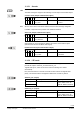
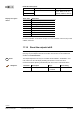
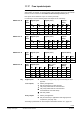
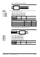
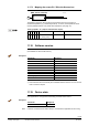
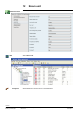
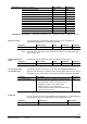
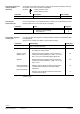
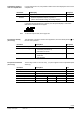
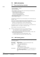
Table Of Contents
- RXB (KNX) applications library
- RXB Description of functions for FC10, FC11, FC12, FC13
- Table of contents
- 1 Introduction
- 2 Definitions / Tools
- 3 Select communication mode
- 4 Applications, parameters
- 5 Room operating modes
- 5.1 Description
- 5.2 Overview
- 5.3 Determine the room operating mode in Desigo (S-mode)
- 5.3.1 Local control of room operating mode via a window contact
- 5.3.2 Central control of room operating mode via input from the Use time schedule
- 5.3.3 Central and local control of room operating modebased on occupancy
- 5.3.4 Central control of room operating mode viathe Room operating mode time schedule
- 5.3.5 Local control of room operating mode with a room unit
- 5.3.6 Local control of room operating mode via the Temporary Comfort mode input
- 5.3.7 Effective room operating mode
- 5.3.8 Desigo examples
- 5.4 Determine the room operating mode with third-party products (S-mode)
- 5.4.1 Local control of room operating mode via the window contact input
- 5.4.2 Central control of room operating mode via the Room operating mode time schedule
- 5.4.3 Central control of room operating mode via the Use and Occupancy time schedules
- 5.4.4 Central and local control of room operating modebased on occupancy
- 5.4.5 Local control of room operating mode with a room unit
- 5.4.6 Local control of room operating mode via the Temporary Comfort mode input
- 5.4.7 Effective room operating mode
- 5.4.8 Third-party (S-mode) examples
- 5.5 Determine the room operating mode with Synco (LTE mode)
- 5.5.1 Local control of room operating mode via the window contact input
- 5.5.2 Central control of the room operating mode via Enable Comfort
- 5.5.3 Central control of room operating mode via Room operating mode input
- 5.5.4 Local control of room operating mode via presence detector
- 5.5.5 Local control of room operating mode with a room unit
- 5.5.6 LTE-Mode Examples
- 5.6 Determine the room operating mode without a bus (stand-alone)
- 6 Setpoint calculation
- 7 Temperature measurement
- 8 Control sequences
- 9 Fan control
- 10 Master/slave
- 11 General and central functions
- 11.1 Send heartbeat and receive timeouts
- 11.2 Digital inputs
- 11.3 Temporary Comfort mode
- 11.4 Presence detector switch-on and switchoff delay
- 11.5 Heating and cooling demand
- 11.6 Heating/cooling signal output
- 11.7 Special functions
- 11.8 Boost heating (Morning Warmup, 2)
- 11.9 Night purge (Night Purge, 4), (FNC10, FNC12)
- 11.10 Precooling (Precool, 5)
- 11.11 Test mode (Test, 7)
- 11.12 Emergency heating (Emergency Heat, 8)
- 11.13 Rapid ventilation (Fan only, 9)
- 11.14 Free cooling (Freecool, 10)
- 11.15 Alarm
- 11.16 Reset the setpoint shift
- 11.17 Free inputs/outputs
- 11.18 Software version
- 11.19 Device state
- 12 Room unit
- 13 KNX information
- 14 FAQs
- 15 Integrate RXB in Desigo/Synco
- 15.1 Case 1: Integration into Synco
- 15.2 Case 2: Integration into Desigo
- 15.3 Case 3: Display in Desigo, with shared Synco time scheduler
- 15.4 Case 4: Display in Desigo/Synco, with shared Synco time scheduler
- 15.5 Case 5: Display in Desigo, andseparate time schedulers
- 15.6 Case 6: Separate display, andseparate time schedulers
- 15.7 Case 7: Separate display, andshared Synco time scheduler
- 16 Working with different tools

151/182
Siemens RXB (KNX) application library RXB Description of functions for FC-10, FC-11, FC-12, FC-13 CM110385en_08
Building Technologies General and central functions 2013-06-17
11.15.1 S-mode
In S-mode, the above described alarms are provided as a common alarm.
The alarm message is mapped to the following S-mode output communication object:
Common alarm (Output communication object)
Flags
Type Send heartbeat States
R
W
C
T
U
1 0 1 1 0 1.005
DPT_Alarm
yes 0 = No alarm
1 = Alarm
As soon as the cause of the alarm ceases to exist, the alarm message disappears.
In addition, output Alarm info provides more detailed information:
Alarm info (Output communication object)
Flags
Type Send heartbeat Info
R
W
C
T
U
1 0 1 1 0 219.001
DPT_AlarmInfo
yes See Konnex specification
Output Alarm info can be enabled or disabled via another communication object:
(this influences also the LTE-Mode alarm signal)
Enable alarm info (Input communication object)
Flags
Type Receive timeout States
R
W
C
T
U
0 1 1 0 0 1.003
DPT_Enable
Ja (fix 42 hours)
0 = Disabled
1 = Enabled
11.15.2 LTE mode
Enable alarm info can be operated in LTE mode. Two further types of information are
provided as outputs: AlarmInfo_CS and AlarmText_CS.
Together with Synco, users do not need to note if the bindings are created
automatically.
Here, the device listens on the bus and sends an alarm when it has highest alarm
priority. This ensures that the management station does not miss any alarms.
AlarmInfo_CS (Output)
Possible partner function blocks Known partner devices
AlarmInfo_CS
Siemens
Synco RMU710 / 20 / 30,
RMH760, RMB795, RMS705
Broadcast
AlarmText_CS (Output)
Possible partner function blocks Known partner devices
AlarmText_CS
Siemens
Synco RMU710 / 20 / 30,
RMH760, RMB795, RMS705
Broadcast
CO
Note