
Operating Instructions
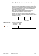
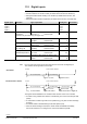
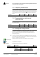
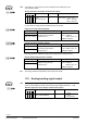

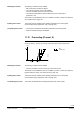
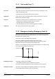
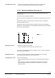
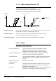
Table Of Contents
- RXB (KNX) applications library
- RXB Description of functions for FC10, FC11, FC12, FC13
- Table of contents
- 1 Introduction
- 2 Definitions / Tools
- 3 Select communication mode
- 4 Applications, parameters
- 5 Room operating modes
- 5.1 Description
- 5.2 Overview
- 5.3 Determine the room operating mode in Desigo (S-mode)
- 5.3.1 Local control of room operating mode via a window contact
- 5.3.2 Central control of room operating mode via input from the Use time schedule
- 5.3.3 Central and local control of room operating modebased on occupancy
- 5.3.4 Central control of room operating mode viathe Room operating mode time schedule
- 5.3.5 Local control of room operating mode with a room unit
- 5.3.6 Local control of room operating mode via the Temporary Comfort mode input
- 5.3.7 Effective room operating mode
- 5.3.8 Desigo examples
- 5.4 Determine the room operating mode with third-party products (S-mode)
- 5.4.1 Local control of room operating mode via the window contact input
- 5.4.2 Central control of room operating mode via the Room operating mode time schedule
- 5.4.3 Central control of room operating mode via the Use and Occupancy time schedules
- 5.4.4 Central and local control of room operating modebased on occupancy
- 5.4.5 Local control of room operating mode with a room unit
- 5.4.6 Local control of room operating mode via the Temporary Comfort mode input
- 5.4.7 Effective room operating mode
- 5.4.8 Third-party (S-mode) examples
- 5.5 Determine the room operating mode with Synco (LTE mode)
- 5.5.1 Local control of room operating mode via the window contact input
- 5.5.2 Central control of the room operating mode via Enable Comfort
- 5.5.3 Central control of room operating mode via Room operating mode input
- 5.5.4 Local control of room operating mode via presence detector
- 5.5.5 Local control of room operating mode with a room unit
- 5.5.6 LTE-Mode Examples
- 5.6 Determine the room operating mode without a bus (stand-alone)
- 6 Setpoint calculation
- 7 Temperature measurement
- 8 Control sequences
- 9 Fan control
- 10 Master/slave
- 11 General and central functions
- 11.1 Send heartbeat and receive timeouts
- 11.2 Digital inputs
- 11.3 Temporary Comfort mode
- 11.4 Presence detector switch-on and switchoff delay
- 11.5 Heating and cooling demand
- 11.6 Heating/cooling signal output
- 11.7 Special functions
- 11.8 Boost heating (Morning Warmup, 2)
- 11.9 Night purge (Night Purge, 4), (FNC10, FNC12)
- 11.10 Precooling (Precool, 5)
- 11.11 Test mode (Test, 7)
- 11.12 Emergency heating (Emergency Heat, 8)
- 11.13 Rapid ventilation (Fan only, 9)
- 11.14 Free cooling (Freecool, 10)
- 11.15 Alarm
- 11.16 Reset the setpoint shift
- 11.17 Free inputs/outputs
- 11.18 Software version
- 11.19 Device state
- 12 Room unit
- 13 KNX information
- 14 FAQs
- 15 Integrate RXB in Desigo/Synco
- 15.1 Case 1: Integration into Synco
- 15.2 Case 2: Integration into Desigo
- 15.3 Case 3: Display in Desigo, with shared Synco time scheduler
- 15.4 Case 4: Display in Desigo/Synco, with shared Synco time scheduler
- 15.5 Case 5: Display in Desigo, andseparate time schedulers
- 15.6 Case 6: Separate display, andseparate time schedulers
- 15.7 Case 7: Separate display, andshared Synco time scheduler
- 16 Working with different tools

150/182
Siemens RXB (KNX) application library RXB Description of functions for FC-10, FC-11, FC-12, FC-13 CM110385en_08
Building Technologies General and central functions 2013-06-17
11.14 Free cooling (Freecool, 10)
This function is used to precool rooms to the Comfort cooling setpoint, in readiness for
normal occupancy. It uses both fan and cooling coil.
This function is meaningful only if low-tariff energy is available.
During occupancy (Comfort / Precomfort) normal mode applies.
3-step fan DC 0...10 V fan
100
TR
10385D28
0
Y [%]
SpH
Cmf
SpC
Cmf
100
TR
10788z09
0
Y [%]
SpH
Cmf
SpC
Cmf
Fan
Cooling coil
The function can be disabled in the room controller by means of P135 or the ETS tool, ,
together with Pre-cooling, see central functions, page 139.
The function must be enabled via the building automation and control system
(communication object Application mode, see page 145).
The function is disabled via the building automation and control system.
11.15 Alarm
Alarms differ in S-mode and LTE mode.
RXB controllers support different alarms:
• Room temperature frost If the room temperature or the return temperature in a fan-coil
application drops below the fixed frost protection limit (5 °C or
adjustable for outside air applications), an alarm is generated.
• Outside air temperature frost In applications with outside air damper, a safety thermostat in the
outside air duct can be connected to the digital input.
• Overheating alarm If the digital input of an RXB22.... controller is used as an overheating
alarm (see page 96), the information is transmitted in this alarm
message.
• Supply air sensor error,
Room sensor error
Sensor fault or short circuit.
• PPS2 fault If the PPS2 communication between a controller and the room unit is
interrupted, or the room unit has an internal fault, the information is
transmitted in this alarm message.
• No air flow If a digital input of an RXB39.1 controller is used for air flow monitoring
(see section 11.2), an alarm is created when the sensor trips.
Enabling the function
Initiating the function
Terminating the function