
Operating Instructions
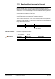
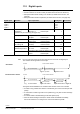
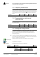
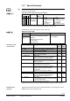

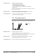
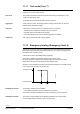
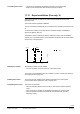
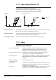
Table Of Contents
- RXB (KNX) applications library
- RXB Description of functions for FC10, FC11, FC12, FC13
- Table of contents
- 1 Introduction
- 2 Definitions / Tools
- 3 Select communication mode
- 4 Applications, parameters
- 5 Room operating modes
- 5.1 Description
- 5.2 Overview
- 5.3 Determine the room operating mode in Desigo (S-mode)
- 5.3.1 Local control of room operating mode via a window contact
- 5.3.2 Central control of room operating mode via input from the Use time schedule
- 5.3.3 Central and local control of room operating modebased on occupancy
- 5.3.4 Central control of room operating mode viathe Room operating mode time schedule
- 5.3.5 Local control of room operating mode with a room unit
- 5.3.6 Local control of room operating mode via the Temporary Comfort mode input
- 5.3.7 Effective room operating mode
- 5.3.8 Desigo examples
- 5.4 Determine the room operating mode with third-party products (S-mode)
- 5.4.1 Local control of room operating mode via the window contact input
- 5.4.2 Central control of room operating mode via the Room operating mode time schedule
- 5.4.3 Central control of room operating mode via the Use and Occupancy time schedules
- 5.4.4 Central and local control of room operating modebased on occupancy
- 5.4.5 Local control of room operating mode with a room unit
- 5.4.6 Local control of room operating mode via the Temporary Comfort mode input
- 5.4.7 Effective room operating mode
- 5.4.8 Third-party (S-mode) examples
- 5.5 Determine the room operating mode with Synco (LTE mode)
- 5.5.1 Local control of room operating mode via the window contact input
- 5.5.2 Central control of the room operating mode via Enable Comfort
- 5.5.3 Central control of room operating mode via Room operating mode input
- 5.5.4 Local control of room operating mode via presence detector
- 5.5.5 Local control of room operating mode with a room unit
- 5.5.6 LTE-Mode Examples
- 5.6 Determine the room operating mode without a bus (stand-alone)
- 6 Setpoint calculation
- 7 Temperature measurement
- 8 Control sequences
- 9 Fan control
- 10 Master/slave
- 11 General and central functions
- 11.1 Send heartbeat and receive timeouts
- 11.2 Digital inputs
- 11.3 Temporary Comfort mode
- 11.4 Presence detector switch-on and switchoff delay
- 11.5 Heating and cooling demand
- 11.6 Heating/cooling signal output
- 11.7 Special functions
- 11.8 Boost heating (Morning Warmup, 2)
- 11.9 Night purge (Night Purge, 4), (FNC10, FNC12)
- 11.10 Precooling (Precool, 5)
- 11.11 Test mode (Test, 7)
- 11.12 Emergency heating (Emergency Heat, 8)
- 11.13 Rapid ventilation (Fan only, 9)
- 11.14 Free cooling (Freecool, 10)
- 11.15 Alarm
- 11.16 Reset the setpoint shift
- 11.17 Free inputs/outputs
- 11.18 Software version
- 11.19 Device state
- 12 Room unit
- 13 KNX information
- 14 FAQs
- 15 Integrate RXB in Desigo/Synco
- 15.1 Case 1: Integration into Synco
- 15.2 Case 2: Integration into Desigo
- 15.3 Case 3: Display in Desigo, with shared Synco time scheduler
- 15.4 Case 4: Display in Desigo/Synco, with shared Synco time scheduler
- 15.5 Case 5: Display in Desigo, andseparate time schedulers
- 15.6 Case 6: Separate display, andseparate time schedulers
- 15.7 Case 7: Separate display, andshared Synco time scheduler
- 16 Working with different tools

142/182
Siemens RXB (KNX) application library RXB Description of functions for FC-10, FC-11, FC-12, FC-13 CM110385en_08
Building Technologies General and central functions 2013-06-17
11.2 Digital inputs
The following volt-free contacts can be connected to digital inputs D1 and D2:
• Presence detector or window contact (for details of this function see Section 5).
• Safety thermostat electric heating coil / reheater (for details of this function, see
page 96).
• Safety thermostat outdoor temperature (for details of this function, see page 109).
Digital input
Function
Type of operation
HandyTool
See section
Input 1
Input 2
Input 3
Input 4
*113
*114
*115
*116
Not used by the
application
Free: Bus = 1 = Contact closed
Free: Bus = 1 = Contact open
0= Default
1
(Contact may be used freely (see page 153 )
Occupancy Occupied = Contact closed
Occupied = Contact open
2
3
Window Window open = Contact open
Window open = Contact closed
4
5
5
Safety thermostat
el. heating coil
Overtemp = Contact open
Overtemp = Contact closed
16
17
8.3
Safety thermostat
Outside temperature
OT < frost = Contact closed
OT < frost = Contact open
(applications with outside air damper only)
32
33
8.5
No air flow
No flow = Contact closed
No flow = Contact open
34
35
see below
Do not connect the same type of sensor/functions to more than one digital input.
The controller would ignore the second input.
t
Fan start No air circulation detected
30 s (debouncing)
Alarm is possible Alarm is issued
30 s (fan start phase)
t
Fan start No air circulation detected
30 s (fan start phase)
Alarm is possible
30 s (debouncing)
Alarm is issued
El. heater disabled El. heater enabled
Fan overrun time
El. heater disabled
Fan off
The figures above illustrate the air circulation alarm function of the room controller:
• An alarm is only possible 30 s after the controller has given a fan command (fan start
phase).
• A closed alarm contact is ignored for 30 s (debouncing), only then an alarm message
is issued.
• An electric heater is disabled during the fan start phase (30 s).
• When an alarm message is issued, the electric heater is disabled immediately;
the fan will continue to run during the fan overrun time defined by P098.
Note
"No airflow"
Function with el. heater