
Operating Instructions
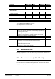
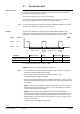
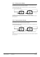
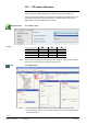
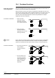
Table Of Contents
- RXB (KNX) applications library
- RXB Description of functions for FC10, FC11, FC12, FC13
- Table of contents
- 1 Introduction
- 2 Definitions / Tools
- 3 Select communication mode
- 4 Applications, parameters
- 5 Room operating modes
- 5.1 Description
- 5.2 Overview
- 5.3 Determine the room operating mode in Desigo (S-mode)
- 5.3.1 Local control of room operating mode via a window contact
- 5.3.2 Central control of room operating mode via input from the Use time schedule
- 5.3.3 Central and local control of room operating modebased on occupancy
- 5.3.4 Central control of room operating mode viathe Room operating mode time schedule
- 5.3.5 Local control of room operating mode with a room unit
- 5.3.6 Local control of room operating mode via the Temporary Comfort mode input
- 5.3.7 Effective room operating mode
- 5.3.8 Desigo examples
- 5.4 Determine the room operating mode with third-party products (S-mode)
- 5.4.1 Local control of room operating mode via the window contact input
- 5.4.2 Central control of room operating mode via the Room operating mode time schedule
- 5.4.3 Central control of room operating mode via the Use and Occupancy time schedules
- 5.4.4 Central and local control of room operating modebased on occupancy
- 5.4.5 Local control of room operating mode with a room unit
- 5.4.6 Local control of room operating mode via the Temporary Comfort mode input
- 5.4.7 Effective room operating mode
- 5.4.8 Third-party (S-mode) examples
- 5.5 Determine the room operating mode with Synco (LTE mode)
- 5.5.1 Local control of room operating mode via the window contact input
- 5.5.2 Central control of the room operating mode via Enable Comfort
- 5.5.3 Central control of room operating mode via Room operating mode input
- 5.5.4 Local control of room operating mode via presence detector
- 5.5.5 Local control of room operating mode with a room unit
- 5.5.6 LTE-Mode Examples
- 5.6 Determine the room operating mode without a bus (stand-alone)
- 6 Setpoint calculation
- 7 Temperature measurement
- 8 Control sequences
- 9 Fan control
- 10 Master/slave
- 11 General and central functions
- 11.1 Send heartbeat and receive timeouts
- 11.2 Digital inputs
- 11.3 Temporary Comfort mode
- 11.4 Presence detector switch-on and switchoff delay
- 11.5 Heating and cooling demand
- 11.6 Heating/cooling signal output
- 11.7 Special functions
- 11.8 Boost heating (Morning Warmup, 2)
- 11.9 Night purge (Night Purge, 4), (FNC10, FNC12)
- 11.10 Precooling (Precool, 5)
- 11.11 Test mode (Test, 7)
- 11.12 Emergency heating (Emergency Heat, 8)
- 11.13 Rapid ventilation (Fan only, 9)
- 11.14 Free cooling (Freecool, 10)
- 11.15 Alarm
- 11.16 Reset the setpoint shift
- 11.17 Free inputs/outputs
- 11.18 Software version
- 11.19 Device state
- 12 Room unit
- 13 KNX information
- 14 FAQs
- 15 Integrate RXB in Desigo/Synco
- 15.1 Case 1: Integration into Synco
- 15.2 Case 2: Integration into Desigo
- 15.3 Case 3: Display in Desigo, with shared Synco time scheduler
- 15.4 Case 4: Display in Desigo/Synco, with shared Synco time scheduler
- 15.5 Case 5: Display in Desigo, andseparate time schedulers
- 15.6 Case 6: Separate display, andseparate time schedulers
- 15.7 Case 7: Separate display, andshared Synco time scheduler
- 16 Working with different tools

132/182
Siemens RXB (KNX) application library RXB Description of functions for FC-10, FC-11, FC-12, FC-13 CM110385en_08
Building Technologies Fan control 2013-06-17
9.7 Periodic fan kick
If the room temperature is measured with a return air sensor in the fan coil (connected
to input B1, see Section 7), the fan must be switched on to ensure that the effective
room temperature is measured correctly.
The function "Periodic fan kick" is used for this purpose.
From version V2.36, a reduced functionality (without time values for Comfort and
Economy) is available even if no return air sensor is parameterized.
For tool architecture reasons, those time values are visible and settable in ACS and in
the HandyTool although not supported by the controller.
The fan can be enabled at the lowest speed at regular intervals. While the room
temperature remains between the effective setpoints SpH and SpC, fan speed 1 / Vmin
is always on for the predefined minimum runtime after expiry of the duty cycle.
RXB2…
Q14 On
Q14 Off
RXB39.1
V min
Off
Y
t [h:mm]
Periodic fan kick Minimum
on time
Periodic fan kick Minimum
on time
Parameter
Basic setting
Range
Resolution
HandyTool
Periodic fan kick Comfort
(RXB39: also PreComfort)
OFF (90 min) 1) 0...89 min ; Off 1) 1 min P096
Periodic fan kick Economy
OFF (360 min) 1)
0...359 min ; Off 1)
1 min
P097
1) HandyTool and ACS: 90 min / 360 min = OFF
RXB39.1: For the min. fan speed settings see section 9.3.
• If the Periodic fan kick is set to 0, then fan speed 1 / Vmin remains on continuously
between the effective setpoints SpH and SpC.
• With a setting of 90 min. (or 360 min), the display changes to "Off".
This indicates that the function is disabled.
• When the measured temperature moves outside the dead band, i.e. above or below
the effective heating/cooling setpoint, the fan switches on before the periodic fan kick
has expired.
• RXB2... : When the room operating mode switches from Economy to Precomfort or
between Precomfort and Comfort, fan speed 1 / Vmin is enabled for the minimum
runtime and the periodic fan kick starts.
• RXB39.1: When the measured temperature moves outside the dead band, i.e.
above the cooling setpoint or below the heating setpoint, the fan switches on before
the periodic fan kick requires it. If there is no demand by a sequence element, the
periodic fan kick is also active outside of the dead zone in order to ensure a correct
return air measurement.
• A QAX34.1 room unit displays the value of B1.
Return air sensor
Note
Function
Notes