
Operating Instructions
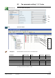
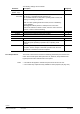
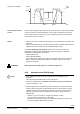
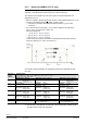
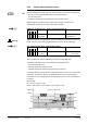
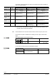
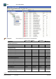
Table Of Contents
- RXB (KNX) applications library
- RXB Description of functions for FC10, FC11, FC12, FC13
- Table of contents
- 1 Introduction
- 2 Definitions / Tools
- 3 Select communication mode
- 4 Applications, parameters
- 5 Room operating modes
- 5.1 Description
- 5.2 Overview
- 5.3 Determine the room operating mode in Desigo (S-mode)
- 5.3.1 Local control of room operating mode via a window contact
- 5.3.2 Central control of room operating mode via input from the Use time schedule
- 5.3.3 Central and local control of room operating modebased on occupancy
- 5.3.4 Central control of room operating mode viathe Room operating mode time schedule
- 5.3.5 Local control of room operating mode with a room unit
- 5.3.6 Local control of room operating mode via the Temporary Comfort mode input
- 5.3.7 Effective room operating mode
- 5.3.8 Desigo examples
- 5.4 Determine the room operating mode with third-party products (S-mode)
- 5.4.1 Local control of room operating mode via the window contact input
- 5.4.2 Central control of room operating mode via the Room operating mode time schedule
- 5.4.3 Central control of room operating mode via the Use and Occupancy time schedules
- 5.4.4 Central and local control of room operating modebased on occupancy
- 5.4.5 Local control of room operating mode with a room unit
- 5.4.6 Local control of room operating mode via the Temporary Comfort mode input
- 5.4.7 Effective room operating mode
- 5.4.8 Third-party (S-mode) examples
- 5.5 Determine the room operating mode with Synco (LTE mode)
- 5.5.1 Local control of room operating mode via the window contact input
- 5.5.2 Central control of the room operating mode via Enable Comfort
- 5.5.3 Central control of room operating mode via Room operating mode input
- 5.5.4 Local control of room operating mode via presence detector
- 5.5.5 Local control of room operating mode with a room unit
- 5.5.6 LTE-Mode Examples
- 5.6 Determine the room operating mode without a bus (stand-alone)
- 6 Setpoint calculation
- 7 Temperature measurement
- 8 Control sequences
- 9 Fan control
- 10 Master/slave
- 11 General and central functions
- 11.1 Send heartbeat and receive timeouts
- 11.2 Digital inputs
- 11.3 Temporary Comfort mode
- 11.4 Presence detector switch-on and switchoff delay
- 11.5 Heating and cooling demand
- 11.6 Heating/cooling signal output
- 11.7 Special functions
- 11.8 Boost heating (Morning Warmup, 2)
- 11.9 Night purge (Night Purge, 4), (FNC10, FNC12)
- 11.10 Precooling (Precool, 5)
- 11.11 Test mode (Test, 7)
- 11.12 Emergency heating (Emergency Heat, 8)
- 11.13 Rapid ventilation (Fan only, 9)
- 11.14 Free cooling (Freecool, 10)
- 11.15 Alarm
- 11.16 Reset the setpoint shift
- 11.17 Free inputs/outputs
- 11.18 Software version
- 11.19 Device state
- 12 Room unit
- 13 KNX information
- 14 FAQs
- 15 Integrate RXB in Desigo/Synco
- 15.1 Case 1: Integration into Synco
- 15.2 Case 2: Integration into Desigo
- 15.3 Case 3: Display in Desigo, with shared Synco time scheduler
- 15.4 Case 4: Display in Desigo/Synco, with shared Synco time scheduler
- 15.5 Case 5: Display in Desigo, andseparate time schedulers
- 15.6 Case 6: Separate display, andseparate time schedulers
- 15.7 Case 7: Separate display, andshared Synco time scheduler
- 16 Working with different tools

128/182
Siemens RXB (KNX) application library RXB Description of functions for FC-10, FC-11, FC-12, FC-13 CM110385en_08
Building Technologies Fan control 2013-06-17
The following example illustrates the effect of the commanded fan value via KNX bus
on the room units's display:
Command
(from KNX bus)
QAX LED
/ cursor
position
Parametrization
Manual (P093 = Manual)
Auto (P093 = Auto, P168 = 1)
Auto (P093 = Auto, P168 = 0)
X = 0%
OpMode: not Comfort
(valves only
1)
)
FanSpeed: 0, BuildProt is active
OpMode: not Comfort
FanSpeed: Auto
e.g. S
minPreCmf
OpMode: not Comfort
(valves only
1)
)
FanSpeed: 0, BuildProt is active
Heating:
0% < X <=23%
Cooling:
0% <
X
<=33.5%
I
OpMode: Comfort
FanSpeed from bus: X
OpMode: Comfort
FanSpeed from bus: X
OpMode: Comfort
FanSpeed from bus: X
Heating:
23% < X <=50%
Cooling:
33.5% < X <=65%
II
OpMode: Comfort
FanSpeed from bus: X
OpMode: Comfort
FanSpeed from bus: X
OpMode: Comfort
FanSpeed from bus: X
Heating:
50% < X <=100%
Cooling:
65% < X <=100%
III
OpMode: Comfort
FanSpeed from bus: X
OpMode: Comfort
FanSpeed from bus: X
OpMode: Comfort
FanSpeed from bus: X
Notes
• Function with FC-10-11-12-13 • Function without P168 for
FC-10-11-12
•
FC-13 with P168 = 1
• Not available with FC-10-11-12
• FC-13 with P168 = 0
1) The valves are controlled with the setpoints of the corresponding operating mode.
A possible electric heater will be disabled.
The time between a bus command and the reaction of the fan may be up to 5-6 sec.
The effective fan speed is available in the following S-mode output communication
object:
Fan output (Output communication object)
Flags
Type Send heartbeat Value
R
W
K
T
U
1 0 1 1 0 5.001
DPT_Scaling
yes 0...100% 0 = 0%
255 = 100%
In LTE mode, the value for the fan is transmitted as follows:
Fan output (Output)
Possible partner function blocks
Known partner devices
FanSpeed
393 UFS
User Fan Speed Setting
---
Geographical zone
Note