
Operating Instructions
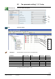
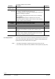
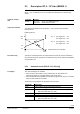
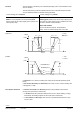
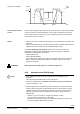
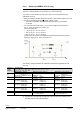
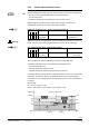
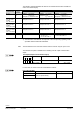
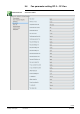
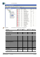
Table Of Contents
- RXB (KNX) applications library
- RXB Description of functions for FC10, FC11, FC12, FC13
- Table of contents
- 1 Introduction
- 2 Definitions / Tools
- 3 Select communication mode
- 4 Applications, parameters
- 5 Room operating modes
- 5.1 Description
- 5.2 Overview
- 5.3 Determine the room operating mode in Desigo (S-mode)
- 5.3.1 Local control of room operating mode via a window contact
- 5.3.2 Central control of room operating mode via input from the Use time schedule
- 5.3.3 Central and local control of room operating modebased on occupancy
- 5.3.4 Central control of room operating mode viathe Room operating mode time schedule
- 5.3.5 Local control of room operating mode with a room unit
- 5.3.6 Local control of room operating mode via the Temporary Comfort mode input
- 5.3.7 Effective room operating mode
- 5.3.8 Desigo examples
- 5.4 Determine the room operating mode with third-party products (S-mode)
- 5.4.1 Local control of room operating mode via the window contact input
- 5.4.2 Central control of room operating mode via the Room operating mode time schedule
- 5.4.3 Central control of room operating mode via the Use and Occupancy time schedules
- 5.4.4 Central and local control of room operating modebased on occupancy
- 5.4.5 Local control of room operating mode with a room unit
- 5.4.6 Local control of room operating mode via the Temporary Comfort mode input
- 5.4.7 Effective room operating mode
- 5.4.8 Third-party (S-mode) examples
- 5.5 Determine the room operating mode with Synco (LTE mode)
- 5.5.1 Local control of room operating mode via the window contact input
- 5.5.2 Central control of the room operating mode via Enable Comfort
- 5.5.3 Central control of room operating mode via Room operating mode input
- 5.5.4 Local control of room operating mode via presence detector
- 5.5.5 Local control of room operating mode with a room unit
- 5.5.6 LTE-Mode Examples
- 5.6 Determine the room operating mode without a bus (stand-alone)
- 6 Setpoint calculation
- 7 Temperature measurement
- 8 Control sequences
- 9 Fan control
- 10 Master/slave
- 11 General and central functions
- 11.1 Send heartbeat and receive timeouts
- 11.2 Digital inputs
- 11.3 Temporary Comfort mode
- 11.4 Presence detector switch-on and switchoff delay
- 11.5 Heating and cooling demand
- 11.6 Heating/cooling signal output
- 11.7 Special functions
- 11.8 Boost heating (Morning Warmup, 2)
- 11.9 Night purge (Night Purge, 4), (FNC10, FNC12)
- 11.10 Precooling (Precool, 5)
- 11.11 Test mode (Test, 7)
- 11.12 Emergency heating (Emergency Heat, 8)
- 11.13 Rapid ventilation (Fan only, 9)
- 11.14 Free cooling (Freecool, 10)
- 11.15 Alarm
- 11.16 Reset the setpoint shift
- 11.17 Free inputs/outputs
- 11.18 Software version
- 11.19 Device state
- 12 Room unit
- 13 KNX information
- 14 FAQs
- 15 Integrate RXB in Desigo/Synco
- 15.1 Case 1: Integration into Synco
- 15.2 Case 2: Integration into Desigo
- 15.3 Case 3: Display in Desigo, with shared Synco time scheduler
- 15.4 Case 4: Display in Desigo/Synco, with shared Synco time scheduler
- 15.5 Case 5: Display in Desigo, andseparate time schedulers
- 15.6 Case 6: Separate display, andseparate time schedulers
- 15.7 Case 7: Separate display, andshared Synco time scheduler
- 16 Working with different tools

127/182
Siemens RXB (KNX) application library RXB Description of functions for FC-10, FC-11, FC-12, FC-13 CM110385en_08
Building Technologies Fan control 2013-06-17
9.3.4 Values representing fan speed
Besides operation via a PPS2 room unit, he fan can also be operated via the KNX bus.
In S-mode, control is shared between two communication objects:
– Fan command value
– Enable fan command value (activates input Fan command value).
When Enable fan command value is disabled, the controller controls the fan
automatically, and the Fan command value input is disabled.
Enable fan command value (Input communication object)
Flags
Type Receive timeout Value
R
W
K
T
U
0 1 1 0 0 1.003
DPT_Enable
no 0 = Disabled / Off
1 = Enabled / On
With FNC03 (electric re-heater) the fan must not be switched off while the re-heater is
active, and a fan overrun must be parameterized, in order to avoid overheating.
Fan command value (Input communication object)
Flags
Type Receive timeout Value
R
W
K
T
U
0 1 1 0 0 5.001
DPT_Scaling
no 0...100% 0 = 0%
255 = 100%
The commanded fan value via KNX bus is handled as an absolute value.
The displayed fan stage on the room unit will be calculated based on
– the commanded fan value
– the room temperature setpoint Comfort
– the parameterized fan speed-ranges (Smin/Smax, heat/cool).
If a commanded fan value (X) results in different fan stages on the room unit for heating
and cooling, the switching will be in the middle of the two active comfort setpoints.
A hysteresis of 0.2 K is implemented to avoid jumping of the room unit cursor between
the stages.
Example with:
S1 = 5%, S2 = 50%, S3 = 80%
SminH = 20%, SmaxH = 80%, SminC = 30%, SmaxC = 100%
CO
Warning!
S
maxH
S
max
C
S
min
C
100%
0%
Sp
CCmf
Sp
HCmf
TR
Speed
(Sp
HCmf +
Sp
CCmf
)/2
0.2 K
0.2 K
X
23%
50%
80%
33.5%
65%
100%
S
minH