
Operating Instructions
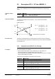
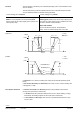
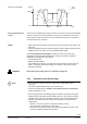
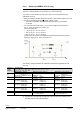
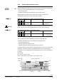
Table Of Contents
- RXB (KNX) applications library
- RXB Description of functions for FC10, FC11, FC12, FC13
- Table of contents
- 1 Introduction
- 2 Definitions / Tools
- 3 Select communication mode
- 4 Applications, parameters
- 5 Room operating modes
- 5.1 Description
- 5.2 Overview
- 5.3 Determine the room operating mode in Desigo (S-mode)
- 5.3.1 Local control of room operating mode via a window contact
- 5.3.2 Central control of room operating mode via input from the Use time schedule
- 5.3.3 Central and local control of room operating modebased on occupancy
- 5.3.4 Central control of room operating mode viathe Room operating mode time schedule
- 5.3.5 Local control of room operating mode with a room unit
- 5.3.6 Local control of room operating mode via the Temporary Comfort mode input
- 5.3.7 Effective room operating mode
- 5.3.8 Desigo examples
- 5.4 Determine the room operating mode with third-party products (S-mode)
- 5.4.1 Local control of room operating mode via the window contact input
- 5.4.2 Central control of room operating mode via the Room operating mode time schedule
- 5.4.3 Central control of room operating mode via the Use and Occupancy time schedules
- 5.4.4 Central and local control of room operating modebased on occupancy
- 5.4.5 Local control of room operating mode with a room unit
- 5.4.6 Local control of room operating mode via the Temporary Comfort mode input
- 5.4.7 Effective room operating mode
- 5.4.8 Third-party (S-mode) examples
- 5.5 Determine the room operating mode with Synco (LTE mode)
- 5.5.1 Local control of room operating mode via the window contact input
- 5.5.2 Central control of the room operating mode via Enable Comfort
- 5.5.3 Central control of room operating mode via Room operating mode input
- 5.5.4 Local control of room operating mode via presence detector
- 5.5.5 Local control of room operating mode with a room unit
- 5.5.6 LTE-Mode Examples
- 5.6 Determine the room operating mode without a bus (stand-alone)
- 6 Setpoint calculation
- 7 Temperature measurement
- 8 Control sequences
- 9 Fan control
- 10 Master/slave
- 11 General and central functions
- 11.1 Send heartbeat and receive timeouts
- 11.2 Digital inputs
- 11.3 Temporary Comfort mode
- 11.4 Presence detector switch-on and switchoff delay
- 11.5 Heating and cooling demand
- 11.6 Heating/cooling signal output
- 11.7 Special functions
- 11.8 Boost heating (Morning Warmup, 2)
- 11.9 Night purge (Night Purge, 4), (FNC10, FNC12)
- 11.10 Precooling (Precool, 5)
- 11.11 Test mode (Test, 7)
- 11.12 Emergency heating (Emergency Heat, 8)
- 11.13 Rapid ventilation (Fan only, 9)
- 11.14 Free cooling (Freecool, 10)
- 11.15 Alarm
- 11.16 Reset the setpoint shift
- 11.17 Free inputs/outputs
- 11.18 Software version
- 11.19 Device state
- 12 Room unit
- 13 KNX information
- 14 FAQs
- 15 Integrate RXB in Desigo/Synco
- 15.1 Case 1: Integration into Synco
- 15.2 Case 2: Integration into Desigo
- 15.3 Case 3: Display in Desigo, with shared Synco time scheduler
- 15.4 Case 4: Display in Desigo/Synco, with shared Synco time scheduler
- 15.5 Case 5: Display in Desigo, andseparate time schedulers
- 15.6 Case 6: Separate display, andseparate time schedulers
- 15.7 Case 7: Separate display, andshared Synco time scheduler
- 16 Working with different tools

125/182
Siemens RXB (KNX) application library RXB Description of functions for FC-10, FC-11, FC-12, FC-13 CM110385en_08
Building Technologies Fan control 2013-06-17
If the fan coil is equipped with a return air sensor, the fan has to run at least periodically
in order to measure a correct temperature. This running is activated by means of the
sensor selection (return air sensor). The fan running time and period can be defined,
see "Periodic fan kick", section 9.7.
• With an active electric heater, min fan speed can not be lower than 10% (safety, see
page 102).
• The fan is disabled when the controller specifies an electric heating output equal to 0
AND the minimum fan switch-on time has elapsed (P098, P159).
If the room operating mode changes (Comfort, Economy etc.) and the room
temperature is within the dead band after the change, the sequence controller is
reinitialized by the application. This implies:
– Valve positions of 0%
– Electric reheater disabled
– Fan is switched off. However, any delay time (minimum switch-on time, switch-off
delay in conjunction with electric heating coil / reheater or periodic fan kick)) is
allowed to expire first.
Please observe the safety notes on el. reheaters on page 102.
9.3.2 Automatic mode (FNC08 only)
• Room supply air cascade control only supports the control strategy "fan in
sequence".
This means that parameters P162...P167 cannot be set.
• The min fan speed values for Comfort, Pre-comfort, Economy and Protection
must be configured to > 0%.
• At low energy demand, the following sequence overrides the minimum fan speed
setting to assure a smoother dynamic behavior of the fan. The sequence reduces
potential cold air flows by using higher air speeds, e.g.in cases of transient valve
positions / fan speeds. Thus the overall user comfort at low energy demand is
usually better.
– Demand < 4%: Fan runs at min. fan speed for heating / cooling.
An overrun timer is started (6 min, fixed value).
– Demand 0%: Fan keeps running at 10% speed (fixed value) if the overrun time
has not yet elapsed. Otherwise the fan stops.
Sequence and parallel
Fan coils with return air
sensor
FNC03
WARNING
STOP
Note!
100%
0%
Fan
Valve
S
maxH
S
minH
Sp
CCmf
Sp
HCmf
S
max
C
TR
S
min
C
X
PFanH
Ofs
FanH
X
PFanC
Ofs
FanC
=
=
Speed