
Operating Instructions
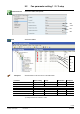
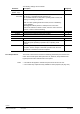
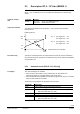
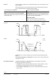
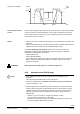
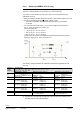
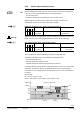
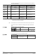
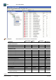
Table Of Contents
- RXB (KNX) applications library
- RXB Description of functions for FC10, FC11, FC12, FC13
- Table of contents
- 1 Introduction
- 2 Definitions / Tools
- 3 Select communication mode
- 4 Applications, parameters
- 5 Room operating modes
- 5.1 Description
- 5.2 Overview
- 5.3 Determine the room operating mode in Desigo (S-mode)
- 5.3.1 Local control of room operating mode via a window contact
- 5.3.2 Central control of room operating mode via input from the Use time schedule
- 5.3.3 Central and local control of room operating modebased on occupancy
- 5.3.4 Central control of room operating mode viathe Room operating mode time schedule
- 5.3.5 Local control of room operating mode with a room unit
- 5.3.6 Local control of room operating mode via the Temporary Comfort mode input
- 5.3.7 Effective room operating mode
- 5.3.8 Desigo examples
- 5.4 Determine the room operating mode with third-party products (S-mode)
- 5.4.1 Local control of room operating mode via the window contact input
- 5.4.2 Central control of room operating mode via the Room operating mode time schedule
- 5.4.3 Central control of room operating mode via the Use and Occupancy time schedules
- 5.4.4 Central and local control of room operating modebased on occupancy
- 5.4.5 Local control of room operating mode with a room unit
- 5.4.6 Local control of room operating mode via the Temporary Comfort mode input
- 5.4.7 Effective room operating mode
- 5.4.8 Third-party (S-mode) examples
- 5.5 Determine the room operating mode with Synco (LTE mode)
- 5.5.1 Local control of room operating mode via the window contact input
- 5.5.2 Central control of the room operating mode via Enable Comfort
- 5.5.3 Central control of room operating mode via Room operating mode input
- 5.5.4 Local control of room operating mode via presence detector
- 5.5.5 Local control of room operating mode with a room unit
- 5.5.6 LTE-Mode Examples
- 5.6 Determine the room operating mode without a bus (stand-alone)
- 6 Setpoint calculation
- 7 Temperature measurement
- 8 Control sequences
- 9 Fan control
- 10 Master/slave
- 11 General and central functions
- 11.1 Send heartbeat and receive timeouts
- 11.2 Digital inputs
- 11.3 Temporary Comfort mode
- 11.4 Presence detector switch-on and switchoff delay
- 11.5 Heating and cooling demand
- 11.6 Heating/cooling signal output
- 11.7 Special functions
- 11.8 Boost heating (Morning Warmup, 2)
- 11.9 Night purge (Night Purge, 4), (FNC10, FNC12)
- 11.10 Precooling (Precool, 5)
- 11.11 Test mode (Test, 7)
- 11.12 Emergency heating (Emergency Heat, 8)
- 11.13 Rapid ventilation (Fan only, 9)
- 11.14 Free cooling (Freecool, 10)
- 11.15 Alarm
- 11.16 Reset the setpoint shift
- 11.17 Free inputs/outputs
- 11.18 Software version
- 11.19 Device state
- 12 Room unit
- 13 KNX information
- 14 FAQs
- 15 Integrate RXB in Desigo/Synco
- 15.1 Case 1: Integration into Synco
- 15.2 Case 2: Integration into Desigo
- 15.3 Case 3: Display in Desigo, with shared Synco time scheduler
- 15.4 Case 4: Display in Desigo/Synco, with shared Synco time scheduler
- 15.5 Case 5: Display in Desigo, andseparate time schedulers
- 15.6 Case 6: Separate display, andseparate time schedulers
- 15.7 Case 7: Separate display, andshared Synco time scheduler
- 16 Working with different tools

123/182
Siemens RXB (KNX) application library RXB Description of functions for FC-10, FC-11, FC-12, FC-13 CM110385en_08
Building Technologies Fan control 2013-06-17
9.3 Description DC 0...10 V fan (RXB39.1)
The fan coil applications with RXB39.1 incorporate continuous automatic fan control
(DC 0…10 V). In addition the fan can be enabled and disabled via a volt-free relay
contact.
Controller
Outputs
RXB39.1
G0 / YC3 DC 0…10 V signal for the fan
Q33 / Q34 Enable relay for the fan
The output characteristic of the fan signal (0…10V) is defined via parameters
P150 and P151.
Output signal YC3
10 V
8 V
2 V
0 V
E.g. 1: Pos. signal min . = 2 V
Pos. signal max. = 8 V
E.g. 2 Pos. signal min . = 8 V
Pos. signal max. = 0 V
Heat demand (from controller)
The relay is activated when the fan speed demand exceeds 4% and it is deactivated
when the demand is 0% (hysteresis). In addition the relay can be enabled and disabled
via parameter P173.
9.3.1 Automatic mode (FNC02 / 03 / 04 only)
Two control strategies are available:
• Fan in sequence (fan speed is only increased when an offset to the room
temperature setpoint is exceeded AND the valve is fully open)
• Fan in parallel (fan speed parallel to the positioning signal of the valve or el. reheater
when the start demand is exceeded)
The strategy can be selected via parameters P160 and P161:
Parameter
Description
P160
(Valve position for) Fan start heating demand
100%
Control Strategy fan in sequence is active for heating
<100% Control Strategy fan in parallel is active for heating
(Recommended value: 20...40%)
P161
(Valve position for) Fan start cooling demand
100%
Control Strategy fan in sequence is active for cooling
<100% Control Strategy fan in parallel is active for cooling
(Recommended value: 20...40%)
Controller outputs
(fan)
Output characteristic
Fan enable relay
2 strategies