
Operating Instructions
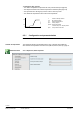
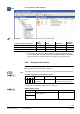
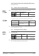
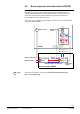
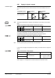
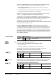
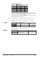
Table Of Contents
- RXB (KNX) applications library
- RXB Description of functions for FC10, FC11, FC12, FC13
- Table of contents
- 1 Introduction
- 2 Definitions / Tools
- 3 Select communication mode
- 4 Applications, parameters
- 5 Room operating modes
- 5.1 Description
- 5.2 Overview
- 5.3 Determine the room operating mode in Desigo (S-mode)
- 5.3.1 Local control of room operating mode via a window contact
- 5.3.2 Central control of room operating mode via input from the Use time schedule
- 5.3.3 Central and local control of room operating modebased on occupancy
- 5.3.4 Central control of room operating mode viathe Room operating mode time schedule
- 5.3.5 Local control of room operating mode with a room unit
- 5.3.6 Local control of room operating mode via the Temporary Comfort mode input
- 5.3.7 Effective room operating mode
- 5.3.8 Desigo examples
- 5.4 Determine the room operating mode with third-party products (S-mode)
- 5.4.1 Local control of room operating mode via the window contact input
- 5.4.2 Central control of room operating mode via the Room operating mode time schedule
- 5.4.3 Central control of room operating mode via the Use and Occupancy time schedules
- 5.4.4 Central and local control of room operating modebased on occupancy
- 5.4.5 Local control of room operating mode with a room unit
- 5.4.6 Local control of room operating mode via the Temporary Comfort mode input
- 5.4.7 Effective room operating mode
- 5.4.8 Third-party (S-mode) examples
- 5.5 Determine the room operating mode with Synco (LTE mode)
- 5.5.1 Local control of room operating mode via the window contact input
- 5.5.2 Central control of the room operating mode via Enable Comfort
- 5.5.3 Central control of room operating mode via Room operating mode input
- 5.5.4 Local control of room operating mode via presence detector
- 5.5.5 Local control of room operating mode with a room unit
- 5.5.6 LTE-Mode Examples
- 5.6 Determine the room operating mode without a bus (stand-alone)
- 6 Setpoint calculation
- 7 Temperature measurement
- 8 Control sequences
- 9 Fan control
- 10 Master/slave
- 11 General and central functions
- 11.1 Send heartbeat and receive timeouts
- 11.2 Digital inputs
- 11.3 Temporary Comfort mode
- 11.4 Presence detector switch-on and switchoff delay
- 11.5 Heating and cooling demand
- 11.6 Heating/cooling signal output
- 11.7 Special functions
- 11.8 Boost heating (Morning Warmup, 2)
- 11.9 Night purge (Night Purge, 4), (FNC10, FNC12)
- 11.10 Precooling (Precool, 5)
- 11.11 Test mode (Test, 7)
- 11.12 Emergency heating (Emergency Heat, 8)
- 11.13 Rapid ventilation (Fan only, 9)
- 11.14 Free cooling (Freecool, 10)
- 11.15 Alarm
- 11.16 Reset the setpoint shift
- 11.17 Free inputs/outputs
- 11.18 Software version
- 11.19 Device state
- 12 Room unit
- 13 KNX information
- 14 FAQs
- 15 Integrate RXB in Desigo/Synco
- 15.1 Case 1: Integration into Synco
- 15.2 Case 2: Integration into Desigo
- 15.3 Case 3: Display in Desigo, with shared Synco time scheduler
- 15.4 Case 4: Display in Desigo/Synco, with shared Synco time scheduler
- 15.5 Case 5: Display in Desigo, andseparate time schedulers
- 15.6 Case 6: Separate display, andseparate time schedulers
- 15.7 Case 7: Separate display, andshared Synco time scheduler
- 16 Working with different tools

118/182
Siemens RXB (KNX) application library RXB Description of functions for FC-10, FC-11, FC-12, FC-13 CM110385en_08
Building Technologies Fan control 2013-06-17
9 Fan control
9.1 Description 1 / 2 / 3-speed fan (RXB2...)
All fan coil applications incorporate single-speed, two-speed or three-speed automatic
fan control. The fan speeds are enabled and disabled via volt-free relay contacts. The
controllers operate with an algorithm optimized for thermal or motorized valve actuators
for each fan speed.
Certain room units allow the user to select the fan speeds MANUALLY (in Comfort
mode only).
There are two types of automatic mode:
• “AUTO” applies to automatic operation at Comfort temperature setpoints.
• The symbol "
" does not mean “Fan Off”, but "automatic operation at reduced
setpoints", e.g. Precomfort mode.
In the reduced room operating modes, the fan speeds CANNOT be selected
manually.
In automatic mode, the fan speeds are controlled in accordance with the response of a
PI controller to the control deviation.
The relays are operated in alternation. Example: When the controller switches from
Speed 1 to Speed 2, first the relay for Speed 1 switches off (A), and then, after a delay
of 1 s, the relay for Speed 2 switches on (B). The same applies in reverse when
switching down.
TR [°C]
Q
SpH
H
10385D19
C
Q14
Y
100%
SpC
Valve sequence
Fan
TR [°C]
SpH
SpC
10385D20
Q14
Q24
(B)
(A)
100%
Y Q
H
a
C
a
Relays switch alternately
Example:
(A) Speed 1 relay OFF
(B) Speed 2 relay ON
after delay of 1 s
TR [°C]
Q
H
10285D21
C
Q14
Q24
Q34
SpH SpC
a
a
Y
100%
Y Output signal
TR Room temperature
SpH Effective heating setpoint
SpC Effective cooling setpoint
H Heating sequence
C Cooling sequence
Q14 1. Fan speed 3
Q24 2. Fan speed 3
Q34 3. Fan speed 3
Room unit
Automatic mode
Single-speed (relay Q14)
2-speed (relays Q14, Q24)
Three-speed (relays
Q14, Q24 and Q34)