
Operating Instructions
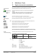
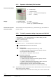
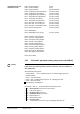
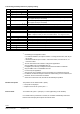
Table Of Contents
- RXB (KNX) applications library
- RXB Description of functions for FC10, FC11, FC12, FC13
- Table of contents
- 1 Introduction
- 2 Definitions / Tools
- 3 Select communication mode
- 4 Applications, parameters
- 5 Room operating modes
- 5.1 Description
- 5.2 Overview
- 5.3 Determine the room operating mode in Desigo (S-mode)
- 5.3.1 Local control of room operating mode via a window contact
- 5.3.2 Central control of room operating mode via input from the Use time schedule
- 5.3.3 Central and local control of room operating modebased on occupancy
- 5.3.4 Central control of room operating mode viathe Room operating mode time schedule
- 5.3.5 Local control of room operating mode with a room unit
- 5.3.6 Local control of room operating mode via the Temporary Comfort mode input
- 5.3.7 Effective room operating mode
- 5.3.8 Desigo examples
- 5.4 Determine the room operating mode with third-party products (S-mode)
- 5.4.1 Local control of room operating mode via the window contact input
- 5.4.2 Central control of room operating mode via the Room operating mode time schedule
- 5.4.3 Central control of room operating mode via the Use and Occupancy time schedules
- 5.4.4 Central and local control of room operating modebased on occupancy
- 5.4.5 Local control of room operating mode with a room unit
- 5.4.6 Local control of room operating mode via the Temporary Comfort mode input
- 5.4.7 Effective room operating mode
- 5.4.8 Third-party (S-mode) examples
- 5.5 Determine the room operating mode with Synco (LTE mode)
- 5.5.1 Local control of room operating mode via the window contact input
- 5.5.2 Central control of the room operating mode via Enable Comfort
- 5.5.3 Central control of room operating mode via Room operating mode input
- 5.5.4 Local control of room operating mode via presence detector
- 5.5.5 Local control of room operating mode with a room unit
- 5.5.6 LTE-Mode Examples
- 5.6 Determine the room operating mode without a bus (stand-alone)
- 6 Setpoint calculation
- 7 Temperature measurement
- 8 Control sequences
- 9 Fan control
- 10 Master/slave
- 11 General and central functions
- 11.1 Send heartbeat and receive timeouts
- 11.2 Digital inputs
- 11.3 Temporary Comfort mode
- 11.4 Presence detector switch-on and switchoff delay
- 11.5 Heating and cooling demand
- 11.6 Heating/cooling signal output
- 11.7 Special functions
- 11.8 Boost heating (Morning Warmup, 2)
- 11.9 Night purge (Night Purge, 4), (FNC10, FNC12)
- 11.10 Precooling (Precool, 5)
- 11.11 Test mode (Test, 7)
- 11.12 Emergency heating (Emergency Heat, 8)
- 11.13 Rapid ventilation (Fan only, 9)
- 11.14 Free cooling (Freecool, 10)
- 11.15 Alarm
- 11.16 Reset the setpoint shift
- 11.17 Free inputs/outputs
- 11.18 Software version
- 11.19 Device state
- 12 Room unit
- 13 KNX information
- 14 FAQs
- 15 Integrate RXB in Desigo/Synco
- 15.1 Case 1: Integration into Synco
- 15.2 Case 2: Integration into Desigo
- 15.3 Case 3: Display in Desigo, with shared Synco time scheduler
- 15.4 Case 4: Display in Desigo/Synco, with shared Synco time scheduler
- 15.5 Case 5: Display in Desigo, andseparate time schedulers
- 15.6 Case 6: Separate display, andseparate time schedulers
- 15.7 Case 7: Separate display, andshared Synco time scheduler
- 16 Working with different tools

11/182
Siemens RXB (KNX) application library RXB Description of functions for FC-10, FC-11, FC-12, FC-13 CM110385en_08
Building Technologies Definitions / Tools 2013-06-17
2 Definitions / Tools
2.1 Signals and parameters (presentation)
The inputs, outputs and parameters of an application can be influenced in various
ways. These are identified by the following symbols in this description of functions:
Parameters identified by this symbol are influenced by the room unit.
Parameters identified by this symbol are set using ETS Professional (EIB tool
software).
The RXB2... KNX controller parameters can be set with ETS3 and later.
The RXB39.1 controller parameters can be set with ETS4 and later.
Parameters identified by this symbol are set with the ACS tool.
ACS V 5.10 and later supports RXB2... ;ACS V8.22 and later supports RXB39.1.
Parameters identified by this symbol are set with the HandyTool tool.
Inputs and outputs identified by this symbol communicate with other KNX devices.
They are called communication objects (CO).
Graphical symbol for an S mode input communication object.
Graphical symbol for an LTE input communication object.
Graphical symbol for an S mode output communication object.
Graphical symbol for an LTE output communication object.
The communication objects of the RXB Konnex controllers work in part in S mode, in
part in LTE mode and in part in both modes. These objects are described accordingly.
The following table describes each communication object working in S-mode:
Time scheduler Use (Input communication object)
Flags
Type
Receive timeout
States
R
W
C
T
U
0 1 1 0 0 20.002
DPT_BuildingMode
yes
0 = In use
1 = Not in use
2 = Protection
(1) Communication object name
Flags: R Read
W Write
C Communication
T Transmit
U Update.
Type Konnex data type
Send heartbeat Yes = Cyclical send
Receive timeout Yes = Cyclical receive (timeout)
States or values Range of states or values which can be adopted
by the send heartbeat communication object
Room unit
ETS Professional
STOP
Note!
ACS
HandyTool
CO
S-mode
communication objects
(1)
Key