
Operating Instructions

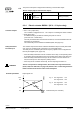

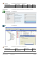
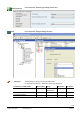
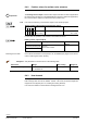
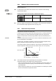
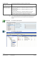
Table Of Contents
- RXB (KNX) applications library
- RXB Description of functions for FC10, FC11, FC12, FC13
- Table of contents
- 1 Introduction
- 2 Definitions / Tools
- 3 Select communication mode
- 4 Applications, parameters
- 5 Room operating modes
- 5.1 Description
- 5.2 Overview
- 5.3 Determine the room operating mode in Desigo (S-mode)
- 5.3.1 Local control of room operating mode via a window contact
- 5.3.2 Central control of room operating mode via input from the Use time schedule
- 5.3.3 Central and local control of room operating modebased on occupancy
- 5.3.4 Central control of room operating mode viathe Room operating mode time schedule
- 5.3.5 Local control of room operating mode with a room unit
- 5.3.6 Local control of room operating mode via the Temporary Comfort mode input
- 5.3.7 Effective room operating mode
- 5.3.8 Desigo examples
- 5.4 Determine the room operating mode with third-party products (S-mode)
- 5.4.1 Local control of room operating mode via the window contact input
- 5.4.2 Central control of room operating mode via the Room operating mode time schedule
- 5.4.3 Central control of room operating mode via the Use and Occupancy time schedules
- 5.4.4 Central and local control of room operating modebased on occupancy
- 5.4.5 Local control of room operating mode with a room unit
- 5.4.6 Local control of room operating mode via the Temporary Comfort mode input
- 5.4.7 Effective room operating mode
- 5.4.8 Third-party (S-mode) examples
- 5.5 Determine the room operating mode with Synco (LTE mode)
- 5.5.1 Local control of room operating mode via the window contact input
- 5.5.2 Central control of the room operating mode via Enable Comfort
- 5.5.3 Central control of room operating mode via Room operating mode input
- 5.5.4 Local control of room operating mode via presence detector
- 5.5.5 Local control of room operating mode with a room unit
- 5.5.6 LTE-Mode Examples
- 5.6 Determine the room operating mode without a bus (stand-alone)
- 6 Setpoint calculation
- 7 Temperature measurement
- 8 Control sequences
- 9 Fan control
- 10 Master/slave
- 11 General and central functions
- 11.1 Send heartbeat and receive timeouts
- 11.2 Digital inputs
- 11.3 Temporary Comfort mode
- 11.4 Presence detector switch-on and switchoff delay
- 11.5 Heating and cooling demand
- 11.6 Heating/cooling signal output
- 11.7 Special functions
- 11.8 Boost heating (Morning Warmup, 2)
- 11.9 Night purge (Night Purge, 4), (FNC10, FNC12)
- 11.10 Precooling (Precool, 5)
- 11.11 Test mode (Test, 7)
- 11.12 Emergency heating (Emergency Heat, 8)
- 11.13 Rapid ventilation (Fan only, 9)
- 11.14 Free cooling (Freecool, 10)
- 11.15 Alarm
- 11.16 Reset the setpoint shift
- 11.17 Free inputs/outputs
- 11.18 Software version
- 11.19 Device state
- 12 Room unit
- 13 KNX information
- 14 FAQs
- 15 Integrate RXB in Desigo/Synco
- 15.1 Case 1: Integration into Synco
- 15.2 Case 2: Integration into Desigo
- 15.3 Case 3: Display in Desigo, with shared Synco time scheduler
- 15.4 Case 4: Display in Desigo/Synco, with shared Synco time scheduler
- 15.5 Case 5: Display in Desigo, andseparate time schedulers
- 15.6 Case 6: Separate display, andseparate time schedulers
- 15.7 Case 7: Separate display, andshared Synco time scheduler
- 16 Working with different tools

109/182
Siemens RXB (KNX) application library RXB Description of functions for FC-10, FC-11, FC-12, FC-13 CM110385en_08
Building Technologies Control sequences 2013-06-17
8.4.4 Radiator valve actuator override
See also section 8.1.7.
For test purposes, the radiator valve actuator can be overridden via the following
communication objects:
Heating surface output override (Input communication object)
Flags
Type Receive timeout Value
R
W
K
T
U
0 1 1 0 0 8.010
DPT_Percent_V16
no 00...100% 0 = 0%
+100 = +100%
+32767 = invalid
Before the radiator valve actuator can be overridden, “Test” mode must be activated via
the communication object Application mode (see page 145).
8.4.5 Downdraft compensation
This function is only active in Comfort mode.
In situations where (owing to large internal heat gains) there is no heating demand from
the room despite a low outdoor temperature (supplied via the bus), large window
surfaces can impair indoor comfort (through radiated cold and the downward flow of
cold air).
A radiator located under the window can be used to “brake” the downward flow of cold
air and compensate for cold radiation.
To achieve this, the radiator is switched on whenever the outdoor temperature drops
below a predefined value (the Outdoor temp. 0% valve position).
The maximum heating output (set under Max. Valve Position) is reached at the "coldest
outdoor temperature" (which can be set under Outdoor temp. max. valve position).
25%
100%
0%
T
OA
Heating output
Outdoor temp.
max. valve position
Max. valve position
10385D17en_01
Outdoor temp.
0% valve position
Thermic
Motoric
The controller adds the values representing the valve position for downdraft
compensation and the valve position for the heating sequence.
– If the room temperature rises as a result of the downdraft compensation feature, the
heating sequence reduces the opening of the associated valve, so correcting the
room temperature.
– When the sequence reaches zero, the room temperature is increased by the residual
heat from the downdraft compensation feature.
CO
Note
Function
Note