
Operating Instructions

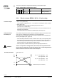

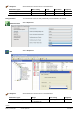
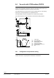
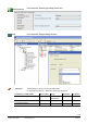
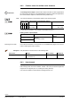
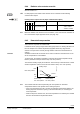
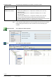
Table Of Contents
- RXB (KNX) applications library
- RXB Description of functions for FC10, FC11, FC12, FC13
- Table of contents
- 1 Introduction
- 2 Definitions / Tools
- 3 Select communication mode
- 4 Applications, parameters
- 5 Room operating modes
- 5.1 Description
- 5.2 Overview
- 5.3 Determine the room operating mode in Desigo (S-mode)
- 5.3.1 Local control of room operating mode via a window contact
- 5.3.2 Central control of room operating mode via input from the Use time schedule
- 5.3.3 Central and local control of room operating modebased on occupancy
- 5.3.4 Central control of room operating mode viathe Room operating mode time schedule
- 5.3.5 Local control of room operating mode with a room unit
- 5.3.6 Local control of room operating mode via the Temporary Comfort mode input
- 5.3.7 Effective room operating mode
- 5.3.8 Desigo examples
- 5.4 Determine the room operating mode with third-party products (S-mode)
- 5.4.1 Local control of room operating mode via the window contact input
- 5.4.2 Central control of room operating mode via the Room operating mode time schedule
- 5.4.3 Central control of room operating mode via the Use and Occupancy time schedules
- 5.4.4 Central and local control of room operating modebased on occupancy
- 5.4.5 Local control of room operating mode with a room unit
- 5.4.6 Local control of room operating mode via the Temporary Comfort mode input
- 5.4.7 Effective room operating mode
- 5.4.8 Third-party (S-mode) examples
- 5.5 Determine the room operating mode with Synco (LTE mode)
- 5.5.1 Local control of room operating mode via the window contact input
- 5.5.2 Central control of the room operating mode via Enable Comfort
- 5.5.3 Central control of room operating mode via Room operating mode input
- 5.5.4 Local control of room operating mode via presence detector
- 5.5.5 Local control of room operating mode with a room unit
- 5.5.6 LTE-Mode Examples
- 5.6 Determine the room operating mode without a bus (stand-alone)
- 6 Setpoint calculation
- 7 Temperature measurement
- 8 Control sequences
- 9 Fan control
- 10 Master/slave
- 11 General and central functions
- 11.1 Send heartbeat and receive timeouts
- 11.2 Digital inputs
- 11.3 Temporary Comfort mode
- 11.4 Presence detector switch-on and switchoff delay
- 11.5 Heating and cooling demand
- 11.6 Heating/cooling signal output
- 11.7 Special functions
- 11.8 Boost heating (Morning Warmup, 2)
- 11.9 Night purge (Night Purge, 4), (FNC10, FNC12)
- 11.10 Precooling (Precool, 5)
- 11.11 Test mode (Test, 7)
- 11.12 Emergency heating (Emergency Heat, 8)
- 11.13 Rapid ventilation (Fan only, 9)
- 11.14 Free cooling (Freecool, 10)
- 11.15 Alarm
- 11.16 Reset the setpoint shift
- 11.17 Free inputs/outputs
- 11.18 Software version
- 11.19 Device state
- 12 Room unit
- 13 KNX information
- 14 FAQs
- 15 Integrate RXB in Desigo/Synco
- 15.1 Case 1: Integration into Synco
- 15.2 Case 2: Integration into Desigo
- 15.3 Case 3: Display in Desigo, with shared Synco time scheduler
- 15.4 Case 4: Display in Desigo/Synco, with shared Synco time scheduler
- 15.5 Case 5: Display in Desigo, andseparate time schedulers
- 15.6 Case 6: Separate display, andseparate time schedulers
- 15.7 Case 7: Separate display, andshared Synco time scheduler
- 16 Working with different tools

102/182
Siemens RXB (KNX) application library RXB Description of functions for FC-10, FC-11, FC-12, FC-13 CM110385en_08
Building Technologies Control sequences 2013-06-17
The power consumption is mapped to the following communication object:
Electric output (Output communication object)
Flags
Type Send heartbeat Value
R
W
K
T
U
1 0 1 1 0 9.024
DPT_Power
yes Floating point (kW)
8.3.4 Electric reheater RXB39.1 (DC 0...10 V plus relay)
• DC 0…10V (output YC1):
The controller is equipped with a 0…10V output for controlling the electric reheater.
• Relay (Q13, Q14):
An additional relay is provided for switching the power on and off
(max load 10 A / 1.8 kW ohmic).
The relay is activated when the demand exceeds 4% and it is deactivated when the
demand is 0% (hysteresis).
This functionality can be enabled and disabled (P099, see page 104).
The controller output of the electric reheater is disabled locally via a safety thermostat
and / or the air circulation input connected to one of the digital inputs.
The safety and air circulation inputs and the way they operate can be configured with
the tool (see "Digital inputs", page 142).
– When the safety thermostat or the air circulation sensor trips, a corresponding alarm
is generated and is transmitted via the communication object Alarm (see page 150).
– When the safety thermostat sensor trips, the fan remains on for the minimum on
time, then it stops if no other sequence (water) is active.
– When only the air circulation sensor trips, the fan output signal remains on.
The min. fan speeds for heating Comfort, Precomfort, Economy and Protection
(P153, P156, P157 and P158, see page 129) must be set to a value that guarantees
that the full heat of the electric heater can be dissipated.
Reheater-parameters
Output signal YC1
10 V
8 V
2 V
0 V
E.g. 1: Pos. signal min . = 2 V
Pos. signal max. = 8 V
E.g. 2 Pos. signal min . = 8 V
Pos. signal max. = 0 V
Heat demand (from controller)
CO
Controller outputs
Safety thermostat
Fan Flow Input
WARNING