
Data Sheet for Product


8/16
Siemens RXB21.1, RXB22.1 Room controllers CM2N3873en_11
Building Technologies 2016-05-18
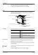
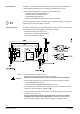
Mounting instructions
The room controllers can be mounted in any orientation, and fixed as follows:
3873J06
3873J07
Rail mounting
The housing base is designed for snap-
mounting on DIN rails, type EN50022-35 x 7.5
(can be released with a screwdriver).
Surface mounting
There are two drill holes for screw-mounting (see “Dimensions” for
drilling template). The housing base is fitted with raised supports.
Screws: Max. diameter 3.5 mm, min. length 38 mm
STOP
Note!
Tightening torque for fixing screws max. 1.5 Nm
When mounting note the following:
• The controller should not be freely accessible after mounting. It must be mounted in
a cabinet or behind a cover that can only be opened / removed with a key or a tool.
• Ensure adequate air circulation to dissipate
heat generated during operation.
• Easy access is required for service personnel
• Local installation regulations must be observed.
Mounting instructions and a drilling template are printed on the controller packaging.
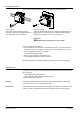
Commissioning
The RXB2... room controllers are commissioned with either the ETS Professional or the
Synco ACS tool
− via the RS232-KNX / EIB interface, or
− via the USB-KNX / EIB interface (OCI700 / OCI702),
or with the HandyTool" via PPS2
The definitive application and the controller's location are handwritten in the labeling
fields "Appl." and "Loc" in the commissioning stage.
A special test mode (ETS Professional or "HandyTool") is available for operation of the
outputs. Further, if the digital inputs have been activated, they can be interrogated.
Labeling
Function test