
Data Sheet for Product


7/16
Siemens RXB21.1, RXB22.1 Room controllers CM2N3873en_11
Building Technologies 2016-05-18
Disposal
The device is considered an electronics device for disposal in terms of European
Directive 2012/19/EU and may not be disposed of as domestic garbage.
• Dispose of the device through channels provided for this purpose.
• Comply with all local and currently applicable laws and regulations.
Engineering notes
The KNX / EIB Building Services Management Manual and system principles supple-
ment (see "Reference documentation", page 11) contains the information relevant for
the engineering of the KNX / EIB bus (topology, bus repeaters, etc.) and for the
selection and dimensions of connecting cables for the supply voltage and field devices.
• The RXB2… room controllers operate with a mains supply voltage of AC 230 V. The
controlled devices (valves and damper actuators) receive their power directly from
the room controller. This means that a separate AC 24 V supply is not necessary for
the controllers and associated field devices.
• The sizing and fuse protection of the power supply cables depends on the total load
and on local regulations. The power supply cables connected to the room controller
must be secured with cable restraints.
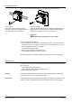
• If serial wiring is applied on the terminal block 19/21, the connection will be inter-
rupted if the block is removed from the controller (the jumpers 19-19 and 21-21 are
on the PCB, not in the block, see terminal diagrams on pages 11 and 12)
• The supply cables must be secured with cable restraints.
• The volt-free relay outputs allow the switching of loads up to AC 250 V, 5 A (4 A).
The heating coil relay in the RXB22.1 switches resistive loads up to 1.8 kW.
The cable dimensions depend on the connected load and the local installation
regulations.
• The circuits must be externally fused (≤ 10 A) as there are no internal fuses.
• The cables connected to the room controller must be secured with cable restraints.
The fans must not be connected in parallel.
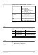
The simultaneous load on outputs Y1 … Y4 must not exceed 9.5 VA.
Y1 (heating) 2 thermic valve actuators, type STP73 5 W
Y2 (cooling) 2 thermic valve actuators, type STP73 5 W
Y3, Y4 (outside air) 3-position damper actuator 4.5 VA 4.5 VA
The maximum load is 9.5 VA for the heating sequence and 9.5 VA for the cooling
sequence.
This is acceptable because the two sequences never operate at the same time.
With low loads (< 2VA) the voltage tolerance may be greater than +20%
(see technical data).
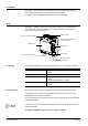
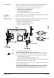
AC 230 V
supply cables
Volt-free
relay outputs
AC 230 V
AC 24 V triac outputs
Example: