
Data Sheet for Product


13/16
Siemens RXB21.1, RXB22.1 Room controllers CM2N3873en_11
Building Technologies 2016-05-18
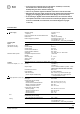
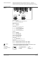
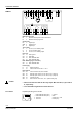
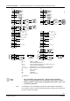
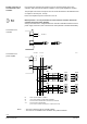
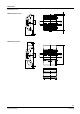
Connection diagrams Connection of field devices, room unit, KNX / EIB bus and power supply
1
2
4
5
6
7
8
9
10
11
12
13
14
15
16
17
18
M
D1
GND
D2
Y1
G
Y2
CP –
CP +
B1
Y3
G
Y4
19
19
21
N
L
N
25
26
27
28
Q13
Q14
Q24
Q34
2
3
1
N
L
N
L
AC 230 V
KNX / EIB
1
N
L
Q1
Q1.1
B2
PPS2
KNX / EIB
Y3
Y4
D1
D2
T
B1
Y3.1
N1
21
L
CE –
CE +
CE –
CE +
1
2
4
3
Y1.2
M
Y3.2
M
1
2
4
5
6
7
8
9
13
14
15
16
17
18
M
D1
GND
D2
Y1
G
Y2
CP –
CP +
B1
19
19
21
N
L
N
25
26
27
28
Q13
Q14
Q24
Q34
N
L
AC 230 V
KNX / EIB
B2
PPS2
KNX / EIB
Y1
Y2
GL
Y1.1
M
N2
3873A11_01
Q43
Q44
23
22
24
21
L
CE –
CE +
CE –
CE +
N.C.
1
2
4
3
Y1.2
M
Y2.2
M
Y1
Y2
GL
Y1.1
M
GL
M
2
3
1
N
L
1
N
L
Q1
Q1.1
L
N
Q2
D1
D2
T
B1
N1 / N2 RXB21.1 / RXB22.1
B1 LG-Ni 1000 temperature sensor
D1, D2 Volt-free contacts (window contact, occupancy sensor, etc.)
Y1...Y4 AC 24 V thermic valve actuators
Y1.1, Y3.1 Motorized AC 24 V, 3-position valve or damper actuator
Y1.2, Y2.2, Y3.2 Electromechanic AC 24 V, 2-position valve actuator
B2 QAX… room unit
Q1 3-speed fan
Q1.1 1-speed fan
Q2 Electric heating coil
Twisted pair
• Fans connected to relay outputs Q14 … Q34 must not be operated in
parallel. For parallel operation use cut-off relays or slave room controllers.
• At Q2 (1.8 kW max. resistive load), use additional external fuses of max. 10 A
to protect the pcb tracks.
For information on the compatibility of field devices with the RXB21.1 and RXB22.1
room controller, refer to the various application descriptions (see the FNC description of
functions, document CA110385)
Note