
Operating Instructions
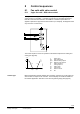
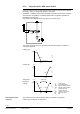
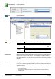
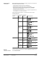
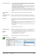
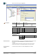
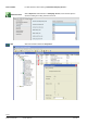
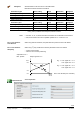
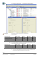
Table Of Contents
- RXB (KNX) applications library
- RXB Description of functions for FC10, FC11, FC12, FC13
- Table of contents
- 1 Introduction
- 2 Definitions / Tools
- 3 Select communication mode
- 4 Applications, parameters
- 5 Room operating modes
- 5.1 Description
- 5.2 Overview
- 5.3 Determine the room operating mode in Desigo (S-mode)
- 5.3.1 Local control of room operating mode via a window contact
- 5.3.2 Central control of room operating mode via input from the Use time schedule
- 5.3.3 Central and local control of room operating modebased on occupancy
- 5.3.4 Central control of room operating mode viathe Room operating mode time schedule
- 5.3.5 Local control of room operating mode with a room unit
- 5.3.6 Local control of room operating mode via the Temporary Comfort mode input
- 5.3.7 Effective room operating mode
- 5.3.8 Desigo examples
- 5.4 Determine the room operating mode with third-party products (S-mode)
- 5.4.1 Local control of room operating mode via the window contact input
- 5.4.2 Central control of room operating mode via the Room operating mode time schedule
- 5.4.3 Central control of room operating mode via the Use and Occupancy time schedules
- 5.4.4 Central and local control of room operating modebased on occupancy
- 5.4.5 Local control of room operating mode with a room unit
- 5.4.6 Local control of room operating mode via the Temporary Comfort mode input
- 5.4.7 Effective room operating mode
- 5.4.8 Third-party (S-mode) examples
- 5.5 Determine the room operating mode with Synco (LTE mode)
- 5.5.1 Local control of room operating mode via the window contact input
- 5.5.2 Central control of the room operating mode via Enable Comfort
- 5.5.3 Central control of room operating mode via Room operating mode input
- 5.5.4 Local control of room operating mode via presence detector
- 5.5.5 Local control of room operating mode with a room unit
- 5.5.6 LTE-Mode Examples
- 5.6 Determine the room operating mode without a bus (stand-alone)
- 6 Setpoint calculation
- 7 Temperature measurement
- 8 Control sequences
- 9 Fan control
- 10 Master/slave
- 11 General and central functions
- 11.1 Send heartbeat and receive timeouts
- 11.2 Digital inputs
- 11.3 Temporary Comfort mode
- 11.4 Presence detector switch-on and switchoff delay
- 11.5 Heating and cooling demand
- 11.6 Heating/cooling signal output
- 11.7 Special functions
- 11.8 Boost heating (Morning Warmup, 2)
- 11.9 Night purge (Night Purge, 4), (FNC10, FNC12)
- 11.10 Precooling (Precool, 5)
- 11.11 Test mode (Test, 7)
- 11.12 Emergency heating (Emergency Heat, 8)
- 11.13 Rapid ventilation (Fan only, 9)
- 11.14 Free cooling (Freecool, 10)
- 11.15 Alarm
- 11.16 Reset the setpoint shift
- 11.17 Free inputs/outputs
- 11.18 Software version
- 11.19 Device state
- 12 Room unit
- 13 KNX information
- 14 FAQs
- 15 Integrate RXB in Desigo/Synco
- 15.1 Case 1: Integration into Synco
- 15.2 Case 2: Integration into Desigo
- 15.3 Case 3: Display in Desigo, with shared Synco time scheduler
- 15.4 Case 4: Display in Desigo/Synco, with shared Synco time scheduler
- 15.5 Case 5: Display in Desigo, andseparate time schedulers
- 15.6 Case 6: Separate display, andseparate time schedulers
- 15.7 Case 7: Separate display, andshared Synco time scheduler
- 16 Working with different tools

89/182
Siemens RXB (KNX) application library RXB Description of functions for FC-10, FC-11, FC-12, FC-13 CM110385en_08
Building Technologies Control sequences 2013-06-17
HandyTool See Parameters in the last column of the table below
Motorized and electromechanical actuators.
Parameters 4-pipe
Basic setting
Range
Resolution
HandyTool
Running time heating valve
150 s
0...360 s
1 s
*061
Running time cooling valve
150 s
0...360 s
1 s
*062
Offset heating valve
0 s
0...360 s
1 s
*071
Offset cooling valve
0 s
0...360 s
1 s
*072
Parameter 2-pipe
Basic setting
Range
Resolution
HandyTool
Running time heating / cooling valve
150 s
0...360 s
1 s
*061 1)
Offset heating valve
0 s
0...360 s
1 s
Offset cooling valve
0 s
0...360 s
1 s
1) In the case of 2-pipe applications (changeover), the parameter *62 (Running time
cooling valve) is visible in the HandyTool, but has no effect.
• For FNC: 10, 12, 18, electromechanical actuators are not allowed for load reasons.
• Also, thermal valves do not have parallel operation of Y1 / Y2 and Y3 / Y4.
When using Siemens Actuators, the parameters are preset and cannot be altered.
When using 3
rd
party actuators the actuator parameters have to be defined:
– runtime of the actuator
– values for min and max positioning
Setpoints for min. /
Max. position
Output signal YC1 / 2
10 V
8 V
2 V
0 V
E.g. 1: Pos. signal min . = 2 V
Pos. signal max. = 8 V
E.g. 2 Pos. signal min . = 8 V
Pos. signal max. = 0 V
Heat / cool demand (from controller)
Select Sequences:
Notes
DC 0...10 V actuators
from Siemens
DC 0...10 V actuators
third-party
ETS Professional