
User Manual


4/14
Siemens Non-communicating room controllers CA2N3881en_02
Building Technologies RXA20.1, RXA21.1, RXA22.1 2012-08-28
Options for use of the labeling fields “Appl.” and “Loc.”:
– Handwritten entry of location and the final application, or
– Printed adhesive label
To avoid incorrect wiring, terminals which can be connected to AC 230 V (supply and
relay outputs) are physically separate from the other terminals.
STOP
Caution
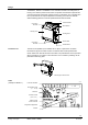
The cable restraints on the housing base must be
used for the connections to terminals 19 … 28
(AC 230 V). The conductors must be secured with
cable ties (see diagram).
80160
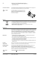
Disposal
The device is classified as waste electronic equipment in terms of the European Direc-
tive 2002/96/EC (WEEE) and should not be disposed of as unsorted municipal waste.
The relevant national legal rules are to be adhered to.
Regarding disposal, use the systems setup for collecting electronic waste.
Observe all local and applicable laws.
Engineering
For information on selecting and sizing the cables for the power supply and for the field
devices, refer to the installation guide, document CA2Z3884. The room controllers have
an AC 230 V mains supply voltage. The controlled devices (valves and damper
actuators) are supplied directly from the room controller. This means that a separate
AC 24 V supply is not necessary for the RXA20.1, RXA21.1 and RXA22.1 controllers
and the associated field devices.
Where several room controllers are operating in the same space, they must be
synchronized via the master/slave interface
Up to 3 slaves may be used (operating in parallel)
The outputs of the master controller are mapped in the slaves. Note that room units
connected to a slave controller cannot be operated
The polarity of the M/S wires has to be respected!
The master/slave interface is compatible with the PRFA and PRFB controllers in the
PRONTO range
Sizing and fuse protection of the supply cables depends on the total load and on local
regulations. The cables must be secured with cable restraints.
The volt-free relay outputs allow switching of loads up to AC 250 V, 5 A (4 A). The
heating coil relay in the RXA22.1 switches resistive loads up to 1.8 kW.
The cable dimensions depend on the connected load and the local installation
regulations. The circuits must be externally fused (max. 10 A) as there are no internal
fuses. The cables must be secured with cable restraints.
STOP
Caution The fans must not
be connected in parallel.
Note
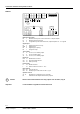
Connection terminals
Master/slave
AC 230 V
supply cables
AC 230 V volt-free
relay outputs