
User guide

RUGGEDCOM ROS
User Guide
Chapter 1
Introduction
ModBus Memory Formats 19
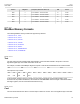
Address #Registers Description (Reference Table in UI) R/W Format
0686 2 Port 4 Statistics – Serial In Packets R Uint32
06C0 2 Port 1 Statistics – Serial Out Packets R Uint32
06C2 2 Port 2 Statistics – Serial Out Packets R Uint32
06C4 2 Port 3 Statistics – Serial Out Packets R Uint32
06C6 2 Port 4 Statistics – Serial Out Packets R Uint32
Section 1.6.3
ModBus Memory Formats
The following ModBus memory formats are supported by Siemens:
• Section 1.6.3.1, “Text”
• Section 1.6.3.2, “Cmd”
• Section 1.6.3.3, “Uint16”
• Section 1.6.3.4, “Uint32”
• Section 1.6.3.5, “PortCmd”
• Section 1.6.3.6, “Alarm”
• Section 1.6.3.7, “PSStatusCmd”
• Section 1.6.3.8, “TruthValues”
Section 1.6.3.1
Text
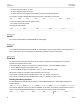
The Text format provides a simple ASCII representation of the information related to the product. The most
significant register byte of an ASCII characters comes first.
For example, consider a Read Multiple Registers request to read Product Identification from location 0x0000.
0x04 0x00 0x00 0x00 0x08
The response may look like:
0x04 0x10 0x53 0x59 0x53 0x54 0x45 0x4D 0x20 0x4E 0x41 0x4D 0x45
0x00 0x00 0x00 0x00 0x00
In this example, starting from byte 3 until the end, the response presents an ASCII representation of the
characters for the product identification, which reads as SYSTEM NAME. Since the length of this field is smaller
than eight registers, the rest of the field is filled with zeros (0).
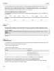
Section 1.6.3.2
Cmd
The Cmd format instructs the device to set the output to either true or false. The most significant byte comes first.