
User guide

RUGGEDCOM ROS
User Guide
Chapter 1
Introduction
ModBus Function Codes 13
Function Code Data
The following sections describe the support for ModBus management:
• Section 1.6.1, “ModBus Function Codes”
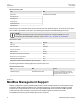
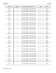
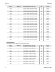
• Section 1.6.2, “ModBus Memory Map”
• Section 1.6.3, “ModBus Memory Formats”
Section 1.6.1
ModBus Function Codes
RUGGEDCOM devices support the following ModBus function codes for device management through ModBus:
NOTE
While RUGGEDCOM devices have a variable number of ports, not all registers and bits apply to all
products.
Registers that are not applicable to a particular device return a zero (0) value. For example, registers
referring to serial ports are not applicable to RUGGEDCOM switch devices.
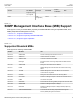
Read Input Registers or Read Holding Registers — 0x04 or 0x03
Example PDU Request
Function Code 1 Byte 0x04(0x03)
Starting Address 2 Bytes 0x0000 to 0xFFFF (Hexadecimal)
128 to 65535 (Decimal)
Number of Input Registers 2 Bytes Bytes 0x0001 to 0x007D
Example PDU Response
Function Code 1 Byte 0x04(0x03)
Byte Count 1 Byte 2 x N
a
Number of Input Registers N
a
x 2 Bytes
a
The number of input registers
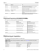
Write Multiple Registers — 0x10
Example PDU Request
Function Code 1 Byte 0x10
Starting Address 2 Bytes 0x0000 to 0xFFFF
Number of Input Registers 2 Bytes Bytes 0x0001 to 0x0079
Byte Count 1 Byte 2 x N
b
Registers Value N
b
x 2 Bytes Value of the register
b
The number of input registers
Example PDU Response
Function Code 1 Byte 0x10