
Installation guide


Installation
4.3 Power Supply Wiring and Grounding
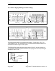
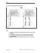
Figure 13: RSG2000 Series Phillips Screw Terminal Block
Philips Screw Terminal without CoverPhilips Screw Terminal with Cover
Safety Cover
Safety Cover
Screws
Chassis Ground
Connection
Surge / Chassis
Ground Jumper
Terminal
Figure 14: RSG2000 Series Phoenix Plug Terminal Block
Phoenix Plug Terminal without CoverPhoenix Plug Terminal with Cover
Safety Cover
Screws
Safety Cover
Chassis Ground
Connection
Terminal
Surge / Chassis
Ground Jumper
The RSG2200 family supports dual redundant power supplies – “Power Supply 1 (PS1)” and
“Power Supply 2 (PS2)”. The connections for PS1, PS2 and the fail-safe relay are located on the
terminal block as shown in Figure 13 and Figure 14.
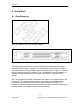
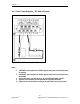
The RSG2000 Family chassis ground connection, shown in Figure 15, uses a #6-32 screw. It is
recommended to terminate the ground connection in a #6 ring lug, and to use a torque setting not
exceeding 15 in.lbs (1.7 Nm).
Figure 15: Chassis Ground Connection
#6 rin
g
lu
g
stainless steel standoff
#6-32 screw with
ext. washer.
16
RuggedCom
®
RuggedSwitch
®
RSG2200 Installation Guide rev115