RuggedSwitch RSG2200 ® 9-Port Modular Managed Gigabit Ethernet Switch Installation Guide June 2, 2011 www.ruggedcom.com RuggedCom Inc.
Copyright COPYRIGHT © 2010 RuggedCom Inc. ALL RIGHTS RESERVED Dissemination or reproduction of this document, or evaluation and communication of its contents, is not authorized except where expressly permitted. Violations are liable for damages. All rights reserved, particularly for the purposes of patent application or trademark registration. This document contains proprietary information, which is protected by copyright. All rights are reserved.
Federal Communications Commission Radio Frequency Interference Statement This equipment has been tested and found to comply with the limits for a Class A digital device pursuant to Part 15 of the FCC Rules. These limits are designed to provide reasonable protection against harmful interference when the equipment is operated in a commercial environment.
Table of Contents Table of Contents 1 2 3 4 5 6 7 8 Table of Figures ...................................................................................................................... 5 Table of Tables........................................................................................................................ 5 Product Overview .................................................................................................................... 6 3.1 Functional Overview...................
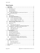
Table of Figures 1 Table of Figures Figure 1: RSG2000 Rack mount chassis orientation options – Front and rear mount...................... 9 Figure 2: Ethernet, LED Status, and Power Panels .......................................................................10 Figure 3: Ethernet panel LED description.......................................................................................10 Figure 4: 1000LX SFP (mini-GBIC) Module and LC connector ......................................................
Product Overview 3 Product Overview 3.1 Functional Overview The RuggedSwitch® RSG2200 is an industrially hardened, fully managed, modular, Ethernet switch specifically designed to operate reliably in electrically harsh and climatically demanding utility substation and industrial environments.
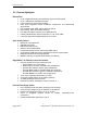
Product Overview 3.2 Feature Highlights Ethernet Ports Up to 9-Gigabit Ethernet ports supporting copper and fiber media Up to 9 100FX Fiber Fast Ethernet ports 2 port modules for tremendous flexibility Fiber types supported include multimode, singlemode, and bidirectional single strand Full compliance with IEEE: 802.3, 802.3u & 802.3z Non-blocking, store and forward switching Full duplex operation and flow control (IEEE 802.
Product Overview Rugged Operating System (ROS®) Networking Features Simple plug and play operation: automatic learning, negotiation, and crossover detection MSTP 802.1Q-2005 (formerly 802.1s) RSTP (Rapid Spanning Tree Protocol) support: IEEE 802.1w eRSTP™ (Enhanced Rapid Spanning Tree) support, <5ms network fault recovery QoS (Quality of Service) support: IEEE 802.1p, for real-time traffic VLAN (Virtual LAN) support: IEEE 802.
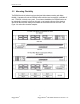
Product Overview 3.3 Mounting Flexibility The RSG2000 series of products have been designed with maximum mounting and display flexibility. Customers can order an RSG2000 series switch that can be mounted in a standard 19” rack, 1” DIN Rail, or directly onto a panel. For rack mount installations, the RSG2000 series can be ordered with connectors on the front of the unit, or can located on the rear of the chassis to allow for all data and power cabling to be installed and connected at the rear of the rack.
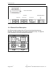
Product Overview Power Terminal Block I/O Ports Ethernet Port Ethernet Ports LED Display Panel Ethernet Ports Figure 2: Ethernet, LED Status, and Power Panels 3.4 Ethernet Panel Description Each Ethernet module is equipped with an LED per port that indicate link/activity status information. The LED will be solid for ports with link, and will blink for activity. The diagram in Figure 3 highlights the port and the associated link/activity LED.
Product Overview 3.4.1 Fiber Optical Transceiver Orientation and Connection Depending on the order code of the product, the RSG2000 series products can be equipped with several different types of fiber optic ports. The Transmit (TX) and Receive (RX) connections of each port must be properly connected and matched for proper link and operation. Modules populated on the top row of the device typically have locking mechanisms or tabs towards the top of the unit.
Product Overview Figure 8: 100FX ST connector 3.5 Display Panel Description The RSG2000 series products are equipped with a versatile display panel, shown in Figure 9, which is designed to provide quick status information for each port, as well as the entire device to allow for simple diagnostics and troubleshooting.
Product Overview Device status LEDs exist to provide a quick visual indicator to operators for operational status of the unit. Table 1 defines the possible LED colours and the corresponding description.
Installation 4 Installation 4.1 Rack Mounting Figure 10: RSG2000 Family 19” Rack Mount Adapters Figure 11: Rack mount adapter mounting location The RSG2000 family of products can be rack mounted using the included rack mount adapter assemblies shown in Figure 10. Secure the rack mount adapter to the front side of the chassis using the included black PAN head Phillips screws in the positions shown in Figure 11. The entire chassis can then be mounted to a standard 19” rack.
Installation 4.2 Panel and DIN Rail Mounting The RSG2200 series products can be ordered as a Panel/DIN mount chassis. Both options involve the use of the panel/DIN adapters to be mounted on each side of the chassis enclosure. The adapter allows for the chassis to be mounted on the standard 1” DIN rail using the grooves in the adapter, secured using the included Phillips screw. See Figure 12 for a PANEL/DIN mount diagram.
Installation 4.
Installation The RSG2200 family can be equipped with either a Phillips Screw Terminal Block or a Phoenix Plug Terminal Block. The Phillips Screw Terminal Block has Phillips screws with a compression plate allowing either bare wire connections or crimped terminal lugs. We recommend the use of #6 size ring lugs to ensure secure, reliable connections under severe shock or vibration. Both terminal blocks have a safety cover which must be removed via two Phillips screws before connecting any wires.
Installation 4.3.1 AC Power Supply Wiring Examples Figure 16: AC Single Power Supply Wiring Example Figure 17: AC Dual Redundant Power Supply Wiring Example Notes: 1. 100-240VAC rated equipment: A 250VAC appropriately rated circuit breaker must be installed. 2. Equipment must be installed according to the applicable country wiring codes. 3. When equipped with two HI voltage power supplies, independent AC sources can be used to power the product for greater redundancy.
Installation 4.3.2 DC Power Supply Wiring Examples Figure 18: DC Power Supply Wiring Examples Notes: 1. 125/250VDC rated equipment: A 300VDC appropriately rated circuit breaker must be installed. 2. A circuit breaker is not required for 12, 24 or 48 VDC rated power supplies. 3. For dual DC power supplies, Separate circuit breakers must be installed and separately identified. 4. Equipment must be installed according to the applicable country wiring codes.
Installation 4.3.3 Dual Power Supplies – DC and AC Inputs Figure 19: DC and AC Power Supply Wiring Examples Notes: 1. 125/250VDC rated equipment: A 300VDC appropriately rated circuit breaker must be installed. 2. 100-240VAC rated equipment: A 250VAC appropriately rated circuit breaker must be installed. 3. A circuit breaker is not required for 12, 24 or 48 VDC rated power supplies. 4. Separate circuit breakers must be installed and separately identified. 5.
Installation 4.4 Dielectric Strength (HIPOT) Testing For dielectric strength (HIPOT) testing in the field, users must remove the metal jumper located on terminal 2, 4, and 6 of the power supply terminal block. This metal jumper connects transient suppression circuitry to chassis ground and must be removed in order to avoid damage to transient suppression circuitry during HIPOT testing. Figure 20 shows the proper HIPOT test connections and should be followed to avoid damage to the device.
Installation 4.5 Failsafe Alarm Relay Wiring and Specifications The “Failsafe” output relay is provided to signal critical error conditions that may occur on the RSG2200 series products. The contacts are energized upon power up of the unit and remain energized until a critical error occurs. The proper relay connections are shown in Figure 21. Control of the output is user selectable and can be programmed via the Rugged Operating System (ROS).
Installation 4.6 Console Port Wiring A RS232 console port for configuration and management of the device is located on the LED display module shown in Figure 22. This port is intended to be a temporary connection during initial configuration or troubleshooting and allows for direct access to the serial-based management console. The connection is made using the DB9-Female to RJ45 console cable included in the device packaging shown in Figure 23.
Installation 4.7 Ethernet Ports 4.7.1 RJ45 Twisted-Pair Data Ports RS2000 series Ethernet switches are equipped with at least 24 10/100BaseTX ports that allow connection to standard CAT-5 UTP cable with RJ45 male connectors. All RS2000 series RJ45 RuggedSwitch products feature auto-negotiation, auto-polarity, and auto-crossover functions. The RJ45 receptacles can also accept and take advantage of screened (commonly known as “shielded”) cabling. Figure 24 shows the RJ45 port pins configuration.
Installation Cabling Category <5 5 1000BaseTx Compliant No Yes Required action New wire infrastructure required Verify TIA/EIA-568-A compliance No action required. New installations should be designed with 5e Yes Category 5e components or higher 6 Yes No action required Connector and cabling standards to be determined. >6 Yes Table 6: Cabling categories and 1000BaseTx compliance defined.
Installation 4.8 Pluggable optics – Installation, removal, and precautions The RSG2000 series of products can be ordered with pluggable optic form factors such as SFP (Small Form-factor Pluggable) or GBIC (Gigabit Interface Converter) modules. These modules can be safely inserted and removed while the chassis is powered and operating – this feature is also known as “hot-swappable”. When inserting or removing optics there are several precautions that should be taken.
Installation 4.8.2 GBIC Module Removal GBIC Modules have two locking latches on either side of the module shown in Figure 26. To remove GBIC module, disconnect any cable and replace with dust cover to protect the optics. User should depress both latches simultaneously and gently pull the module from the chassis. The module should be immediately stored in an ESD-safe environment. Figure 26: Locking latch location on GBIC optical modules 4.8.
Technical Specifications 5 Technical Specifications 5.1 Power Supply Specifications Power Supply Type Input Range Min Max Internal Fuse Rating 6.3A(F) 2 3.15A(T) 2 Max. Power Consumption3 12 – 24 VDC 10 VDC 36 VDC 48 VDC 36 VDC 59 VDC 22W 1 HI (125/250 VDC) 88 VDC 300 VDC 2A(T) 1,2 HI (110/230 VAC) 1 85 VAC 264 VAC NOTES: 1. This is the same power supply for both AC and DC. 2. (F) Denotes fast-acting fuse, (T) denotes time-delay fuse. 3. Power consumption varies based on configuration.
Technical Specifications 5.4 Copper Ethernet Port Specifications The RSG2200 can be ordered with two-port 10/100/1000Tx modules in slots 1, 2, 3, and 4, and a one-port 10/100/1000Tx module in 5. All copper ports have the following specifications: Parameter Specification Notes Speed Duplex Cable-Type Wiring Standard Max Distance Connector Isolation 10/100/1000 Mbps FDX / HDX > Category 5 TIA/EIA T568A/B 100m RJ45 1.
Technical Specifications 5.6.2 Gigabit Ethernet (1000Mbps) Optical Specifications 5.6.2.1 Fixed Gigabit Transceivers Order Code Mode Connector Type FG01 MM LC FG02 FG03 FG04 FG05 SM SM SM SM SC LC SC LC Cable Type (um) 50/125 62.5/125 9/125 9/125 9/125 9/125 Tx λ (typ.) (nm) Tx min (dBm) Tx max (dBm) Rx Sensitivity (dBm) Rx Saturation (dBm) Distance (typ.) (km) Power Budget (dB) 850 -9 -2.5 -20 0 0.5 11 1310 1310 1310 1310 -10 -9.
Technical Specifications 5.7 Operating Environment Parameter Range Ambient Operating Temperature -40 to 85C Ambient Relative Humidity Ambient Storage Temperature RuggedCom® 5% to 95% Comments Ambient Temperature as measured from a 30cm radius surrounding the center of the enclosure.
Technical Specifications 5.8 Mechanical Specifications Parameter Dimensions Value 18.29 x 12.14 x 1.75 inches (464.57) x (308.36) x (44.45) mm Weight Enclosure Comments (Length x Width x Height) with mounting brackets installed 10 lb (4.
Type Tests 6 Type Tests 6.1.1 IEC 61850-3 Type Tests Test Description IEC 61000-4-2 ESD IEC 61000-4-3 Radiated RFI IEC 61000-4-4 Burst (Fast Transient) IEC 61000-4-5 Surge IEC 61000-4-6 Induced (Conducted) RFI IEC 61000-4-8 Magnetic Field IEC 61000-4-29 Voltage Dips & Interrupts IEC 61000-4-11 Test Levels Enclosure Contact Enclosure Air Enclosure ports Signal ports D.C. Power ports A.C. Power ports Earth ground ports Signal ports D.C. Power ports A.C. Power ports Signal ports D.
Type Tests 6.1.2 IEEE 1613 Type Tests IEEE Test IEEE 1613 Clause C37.90.3 9 ESD C37.90.2 8 Radiated RFI C37.90.1 7 Fast Transient C37.90.1 7 Oscillatory C37.90 6 H.V. Impulse C37.90 6 Dielectric Strength Description Test Levels Enclosure Contact Enclosure Air Enclosure ports Signal ports D.C. Power ports A.C. Power ports Earth ground ports Signal ports D.C. Power ports A.C. Power ports Signal ports D.C. Power ports A.C. Power ports Signal ports D.C. Power ports A.C.
Agency Approvals 7 Agency Approvals Agency CSA Standards CSA C22.2 No. 60950, UL 60950 CE EN 60950, EN 61000-6-2 FCC CISPR FDA/CDRH IEC/EN FCC Part 15, Class A EN55022, Class A 21 CFR Chapter 1, Subchapter J EN60825-1:1994 + A11:1996 + A2:2001 Comments Passed CE Compliance is claimed via Declaration of Self Conformity Route Passed Passed Passed Passed 8 Warranty RuggedCom warrants this product for a period of five (5) years from date of purchase. For warranty details, visit http://www.ruggedcom.